
| Newsletter
Home | ECR Homepage |
ECR Shop
| ECR
YouTube | ECR
Groups.io | ECR Facebook |
May 2, 2022
SO, WHAT'S NEW? - By Michael K2SHF If you weren't already aware, The newsletter finally has a permanent home. The URL is http://news.eastcoastreflector.com. The other links that we have been using will eventually cease to exist. So please update your bookmarks accordingly when you can.  Steve, K2EJ, has been working hard behind the scenes to get us some ECR name badges. His work has paid off, and you can now order yours at https://thesignman.com/clubs/eastcoastreflector.html. The ECR makes no money on these, so the price you see (currently $13.50 without options) all goes to the maker of the badges. The options available are pretty cool too, so check it out and see if this is something you'd like to add to your ECR swag.  MORNING BREW Q&A - By Michael K2SHF Thank you to all who checked in to the Morning Brew. The following are answers to some of our recent daily questions. We asked the following questions. As always, only answers with a tally of 2 or more were included below. Thanks to Derby Dan (KD2VNU) for his hard work in logging the answers and tallying the results after each net. 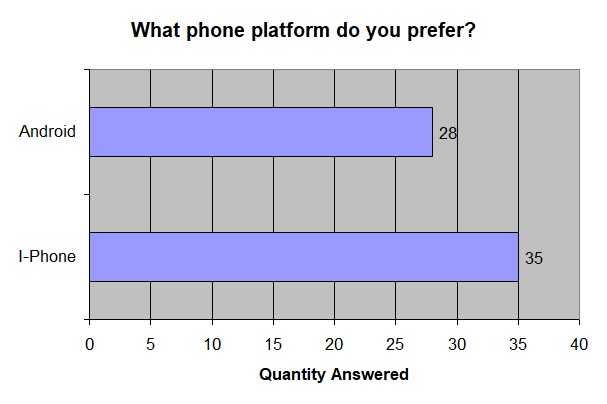 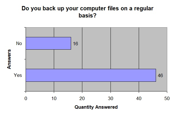 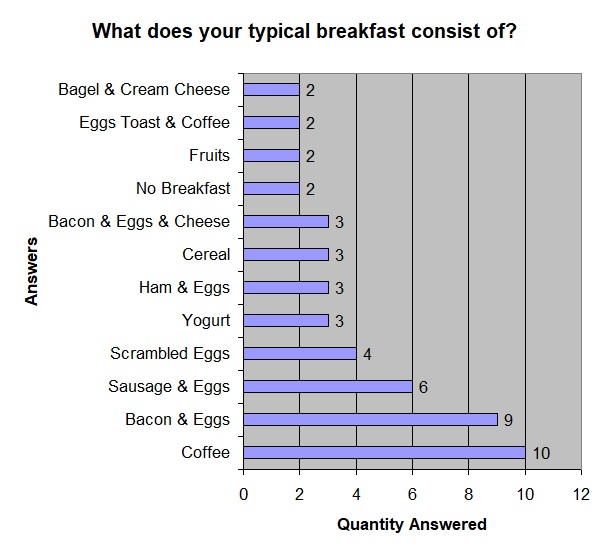   ECR BIRTHDAYS The following hams are celebrating a birthday over the next week. Happy Birthday to you all! KA5OUG, Charles of Tulsa OK, has a birthday on Wednesday, May 4th KD2TRG, Bob of Stony Brook NY, has a birthday on Thursday, May 5th KD6DHR, Bruce of Wheatland CA, has a birthday on Thursday, May 5th Would you like your birthday recognized in the Newsletter and on the air during the Tech Net? Just send an email to K2SHF(at)ARRL(dot)NET with your callsign and birthdate. Your birthday will then be added to our spreadsheet. 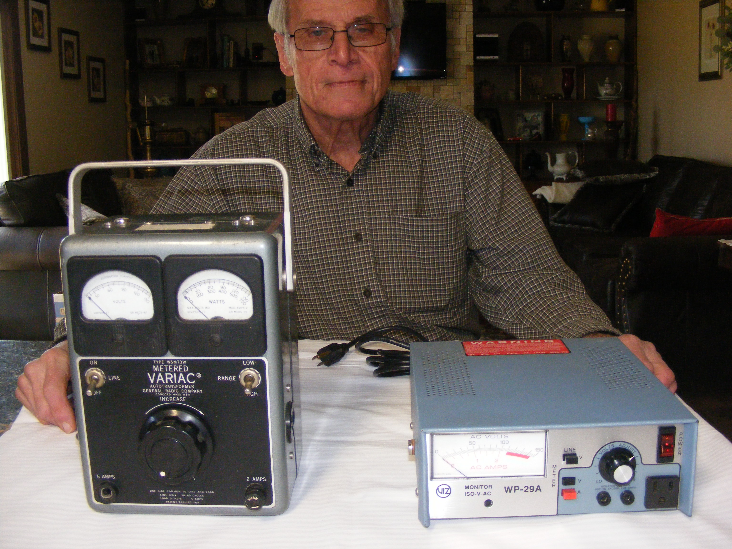 WORK BENCH SAFETY: VARIAC OR ISOLATION TRANSFORMER? CURRENT LIMITED? By Henry WB4IVB My last article mentioned the use of a Variac (Variable AC Voltage Supply) for testing equipment. A Variac allows bringing the AC voltage up gradually instead of just plugging in the line cord, and turning on the power switch. This prevents a full line voltage surge to the device. A Variac uses a transformer, and if you were to measure resistance of the output windings, it would be near zero, because the output is from an inductive device, not resistive. Most Variacs have a voltmeter to indicate the output voltage, and an ammeter to indicate current being supplied to the device under test. 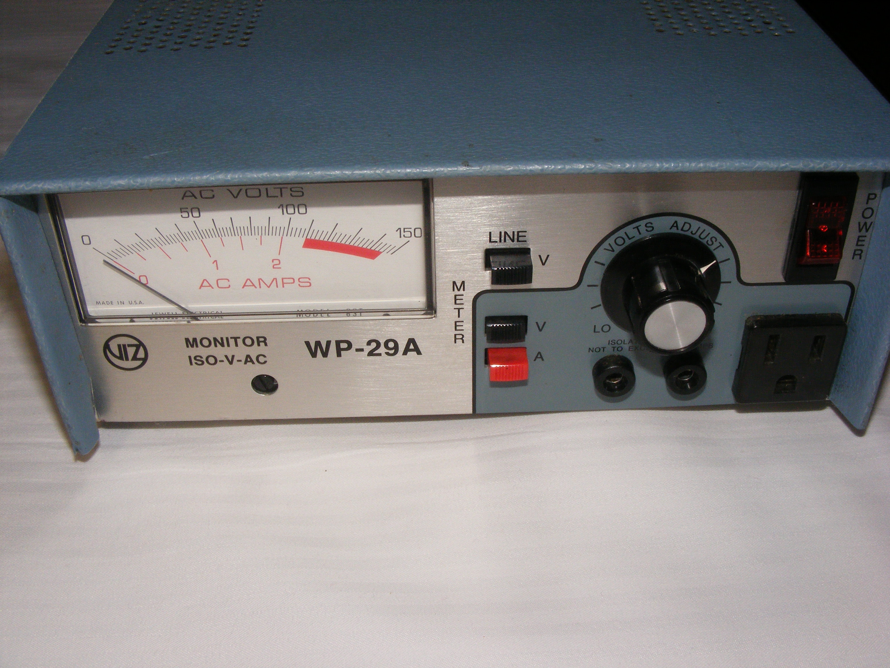 One may think that a Variac isolates the 110 VAC line from the output,
but many do not. If you own a Variac you may notice that it has a
standard three prong ac cord, and an outlet with ground on the front or
side. If this is the case, the input is not isolated from the line
input side unless it provides separate access points to the secondary
windings.
One may think that a Variac isolates the 110 VAC line from the output,
but many do not. If you own a Variac you may notice that it has a
standard three prong ac cord, and an outlet with ground on the front or
side. If this is the case, the input is not isolated from the line
input side unless it provides separate access points to the secondary
windings.Standard U.S power company mains supply 220-240 VAC to the customers meter base, and service panel. Two “hot” and one “neutral”. The neutral wire is grounded both at the meter base and the transformer/pole. A 110-vac duplex outlet will have a hot (black), neutral (white), and a bare ground. If you were to trace these wires back to your service panel (breaker box) you would see that the black wire connects to one of the hot buss bars, and the 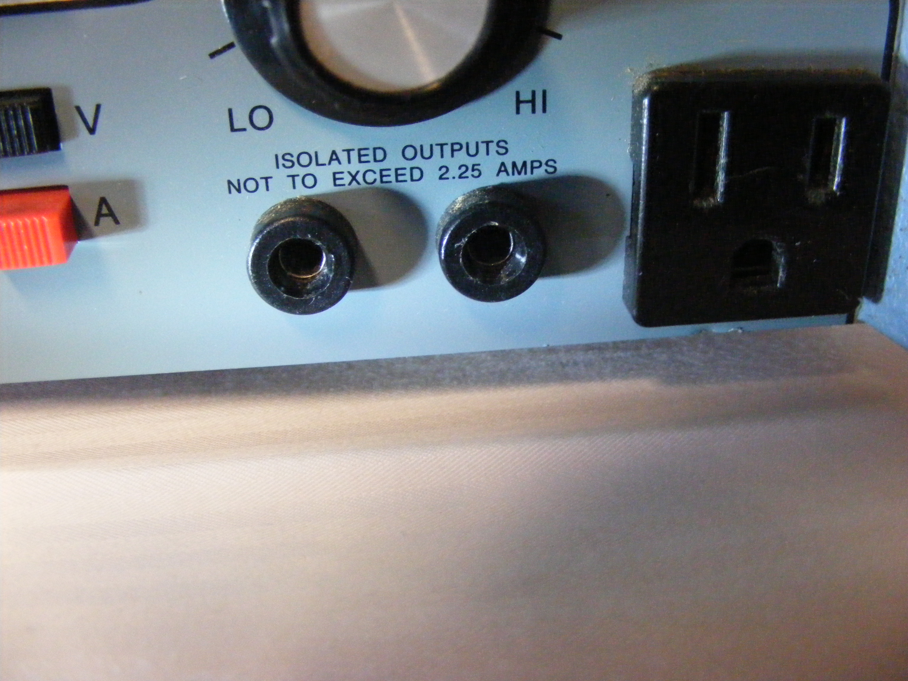 white neutral wire “and” the ground (bare) wire connect to the same
breaker panel bus bar. So, since the Neutral wire and the Ground
are connected together in the service panel, the two wires are at the
same potential.
white neutral wire “and” the ground (bare) wire connect to the same
breaker panel bus bar. So, since the Neutral wire and the Ground
are connected together in the service panel, the two wires are at the
same potential. Why does it matter that Neutral and Ground are at the same potential on my Variac? Some equipment has what is referred to as a “hot chassis”, which is can be found in both new and older electronics. This type of equipment will have an insulated case or cabinet. However, once inside the unit, the chassis becomes exposed. Suppose you were troubleshooting an older tube type radio that did not have a transformer, and no polarized line cord. Using an oscilloscope plugged into an outlet for example, you would normally connect the scope probe ground lead to the chassis, and then the 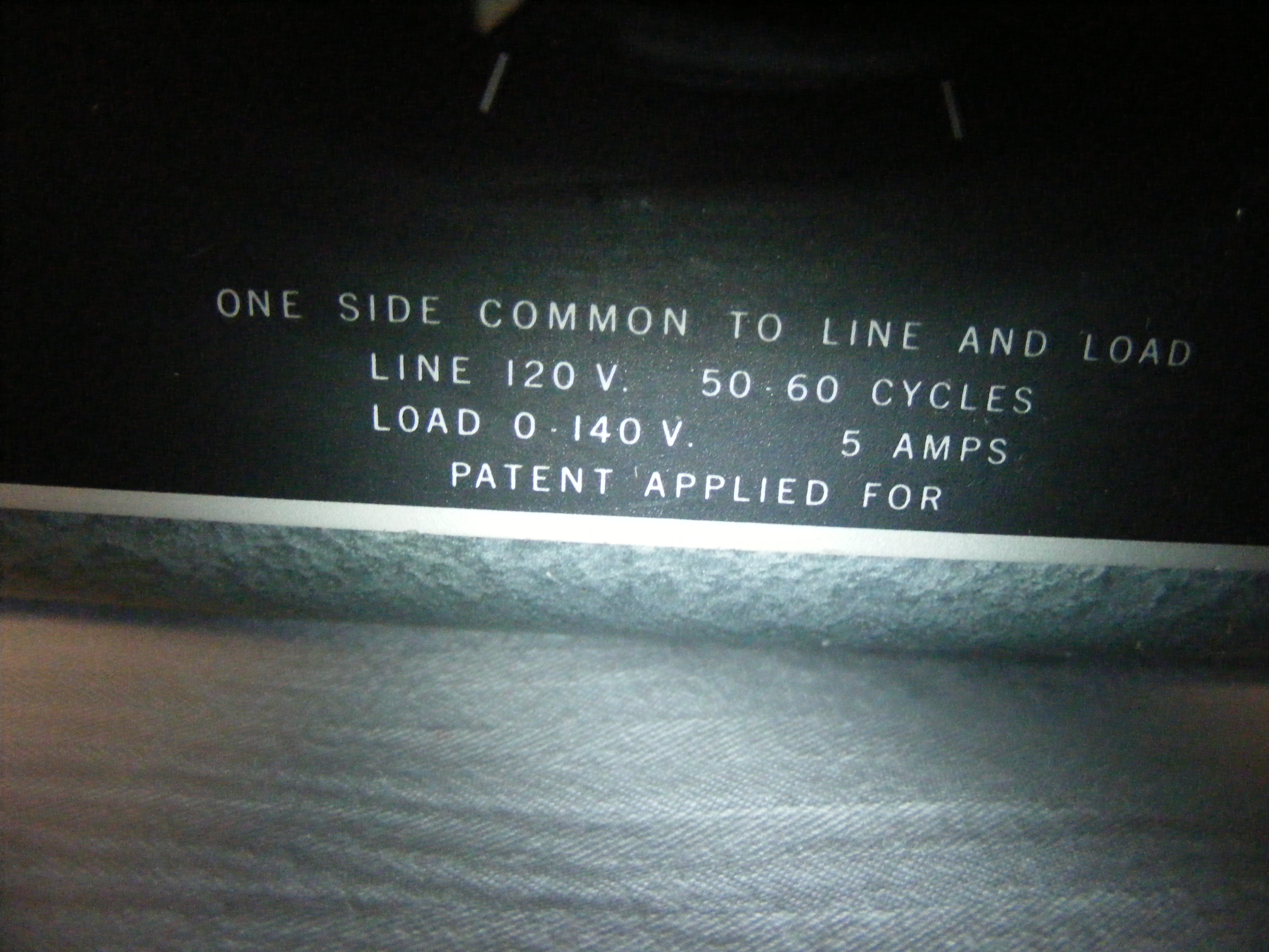 probe tip to the desired test point location. Big problem, you may have
just given the supply voltage a path to ground via your ground test
lead. So, my point here is although some Variacs have “isolation”, many
do not. Be careful!!
probe tip to the desired test point location. Big problem, you may have
just given the supply voltage a path to ground via your ground test
lead. So, my point here is although some Variacs have “isolation”, many
do not. Be careful!!A true Isolation Transformer uses what is called “Galvanic Isolation”. The primary and secondary windings are completely separate, no physical connection. The transformer core separates the two. A quality transformer will have several metal plates, and high insulation material, and will be notably heavy for its physical size. For the test bench a one-to-one (1:1) ratio is common. This means the primary and secondary have the same number of turns, producing by induction, an output voltage the same as the input voltage. Note that the device under test is the only device 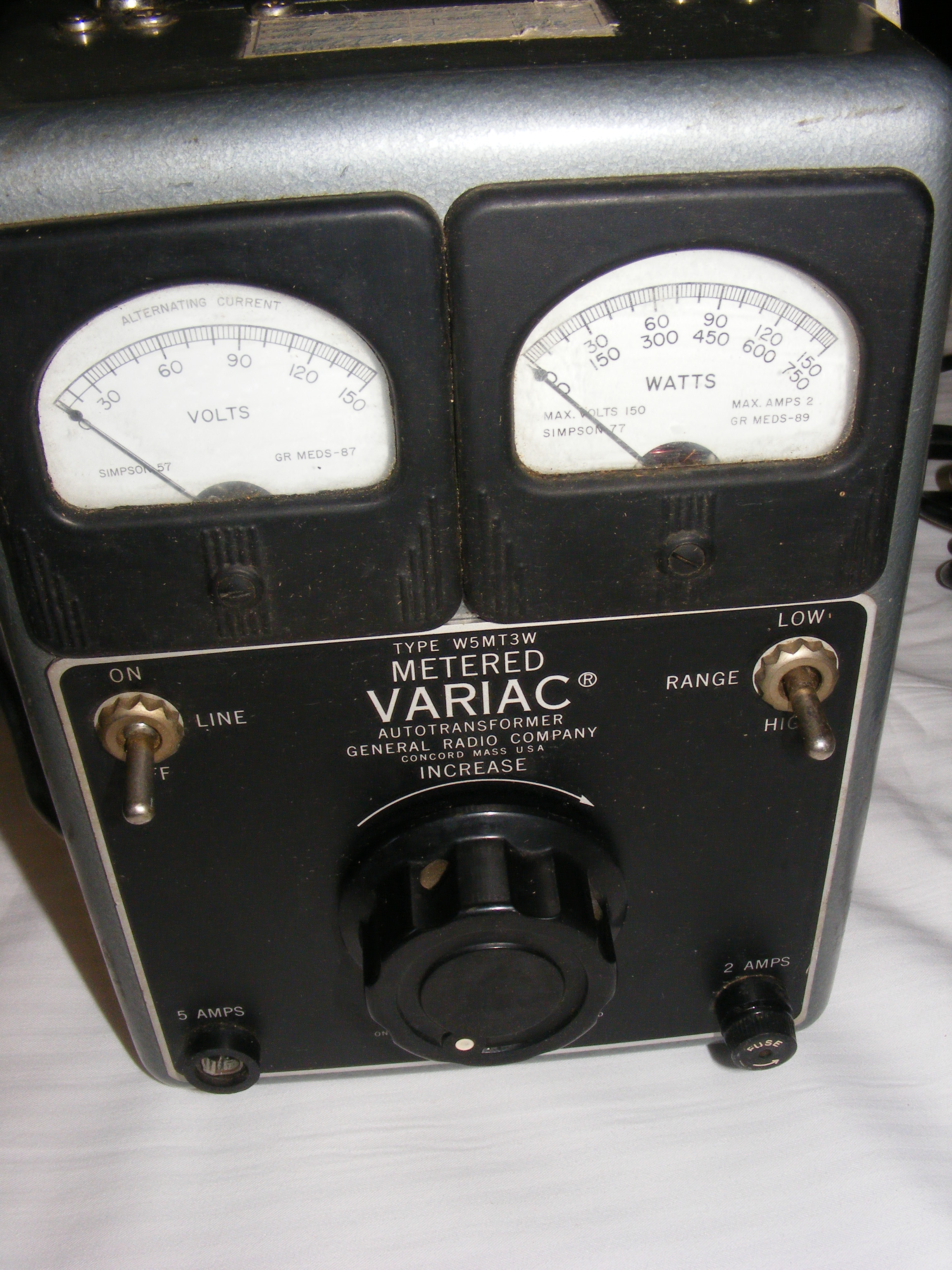 connected to the isolation transformer. Your test equipment should not
be connected to the isolation transformer. The test equipment is now
isolated from the device under test, and one can safely take
measurements. This is not to say that you have eliminated the chance to
short out something or receive an electrical shock, only that you have
isolated the two voltage sources, the test equipment and the device
being tested.
connected to the isolation transformer. Your test equipment should not
be connected to the isolation transformer. The test equipment is now
isolated from the device under test, and one can safely take
measurements. This is not to say that you have eliminated the chance to
short out something or receive an electrical shock, only that you have
isolated the two voltage sources, the test equipment and the device
being tested.So now we have a Variac and an Isolation Transformer, anything else we can add for protection? Most Variacs only limit the AC voltage output by physical rotation of the voltage output control, not current other than a fused input and output. The Isolation Transformer provides much needed isolation, but no current limiting. So, let's assume you have a device under test, you are probing a positive voltage point and get distracted or the probe slips and contacts ground while still on the positive point. Obviously, you have created a short circuit, and you are at the mercy of a fuse or circuit breaker to open the circuit and stop the arcing, melting, and smoking. Current limiting/Current Sharing can be accomplished with a simple incandescent light bulb and socket. A 150-200 Watt light bulb makes an excellent current limiter for the test bench. Very simple to make yourself, and it could save your equipment or even your life. The 150-200 Watt bulb simply needs to be in “series” with the device that you wish to current limit. By being in series, the voltage/current must flow through the bulb, and then to the device. Since a bulb filament has a very high resistance, it limits the amount of current that can be passed. Of course, the same principle could be accomplished with a resistor, but the “bulb filament” gives a visual indication when excess current is flowing in the circuit. The greater the current flow, the brighter the filament and vice-versa. If a “dead short” were to occur, the bulb would have full line voltage applied across the filament. In practical use on the test bench the bulb/socket can be mounted and wired in an electrical box with a series connection to a duplex outlet. If desired you could have two light bulb sockets in parallel, but staying in series with the device, to allow lower wattage bulbs to be used. A “bypass switch” can be connected across the bulb socket/sockets terminals. When the switch is off, the current flows through the bulb filament/filaments providing protection as above. When the switch is on, bulb terminals shorted, and the bulb/bulbs no longer limit current/voltage, relying on any fuses to stop excessive current flow. My WP-29A is a Variac “with” an isolated output. Notice that the 110 vac plug on the front panel has a ground connection, and “Is Not” isolated from the three-prong line cord input. But, the two small banana style receptacles are isolated because they have no physical connection to the input neutral or ground. The General Radio Variac pictured is a well-built, quality instrument, but has no isolation. In their wisdom and as a safety concern, General Radio notes this on the panel. (See Pic) Do not expect all manufacturers to do this. A perfect scenario now is to incorporate all three, Isolation Transformer, Variac, and Current Limiter. If you have a suspect fault or unknown condition on the test bench this allows for safer troubleshooting and checking for issues. I connect my items in the following order: AC Line Input to the solation Transformer, Variac, and a single bulb for Current Limiting. If you were to have an isolation transformer with multiple taps, where different voltages could be accessed, then you could place the Variac, Current Limiter Bulb, before the Isolation transformer. The main goal is to have the device being tested AC isolated from the test equipment AC. Of course, there are single self-contained devices available that combine all three of the above (Variac-Isolation-Current limiting) and metered, in one neat package. But often the individual items like the quality Variacs and Isolation Transformers can be found at Hamfest at reasonable prices and can be used together to create the same electrical equivalent. By the way, never try to use a “Light Dimmer” or a “Resistive Rheostat” as a Variac, or substitute LED bulbs for the Incandescent bulbs as a current limiters. Henry Hamblin WB4IVB  THE ANTENNA FARM - By Charles KC6UFM Part 4 – SWR...Why You Should Not Use It...And Why You Should Use It Hello ECR Family, and welcome to The Antenna Farm. This is your friendly Antenna Farmer Charles, KC6UFM. Yes, I know...that title may be a bit confusing, but simply put, there are many reasons why you should not use SWR for anything and at least one extremely good reason why you should use it everyday. SWR is a big subject, so this entire article will be devoted to helping you understand SWR and other closely related ideas a little better. As is my habit, I will introduce the ideas in a simple way that may, in some cases, be an oversimplification. The game plan is as we move deeper into the dirt here at the Farm, we will correct the simplifications and get more precise with the concepts. This article is likely to be the longest in the series as well. Let’s dig in! SWR stands for “Standing Wave Ratio” and it is, as the name states, a ratio comparing two values, similar to the way a decibel works. In technical terms, there are three types of SWR that are (or have been) of interest: (1) Voltage SWR (or vSWR); (2) Power SWR (or pSWR); and (3) Current SWR (or iSWR). For our use, pSWR and iSWR are almost never used outside of a physics lab. In practice, the only one that matters and the only one we will talk about here is vSWR. In common usage, when you see “SWR”, it can be safely assumed that we are talking about vSWR. If you would like to calculate vSWR yourself (for some reason...maybe you like headaches) I’ll refer you to the rather good article on SWR on Wikipedia. If, however, you aren’t comfortable with mathematical concepts like imaginary numbers, vector analysis, and other more esoteric constructions, just ignore this entire paragraph. What vSWR tells you is how well the feed line (coax or open wire) impedance is matched to the load (antenna) impedance. This is important because ONLY when the impedance of the feed line and the antenna are exactly equal will maximum energy be transferred into the load. Any other condition results in power being wasted as heat in the feed line. Essentially, a particular vSWR value is a comparison between the Forward Voltage (energy sent from the transmitter to the antenna) and the Reflected (or Reverse) Voltage (energy that comes from the antenna toward the transmitter). The forward voltage is easy to understand...this is simply the energy created by your transmitter that is sent toward the antenna via the feed line. The reflected voltage is, however, a little harder to grasp...this is the energy that, when it meets the interface between the feed line and the antenna, literally bounces back down the feed line toward the transmitter. Yes, for the purists, this is a simplification and the actual calculation is more complex, but for our needs, this does the trick. As you probably have reasoned out, there can be an infinite number of values for the resulting vSWR because there are an infinite number of values for the forward and reflected voltages. In practice, we tend to ignore the fine details in the value of vSWR, especially when the result gets big. And that leads to the First Rule of vSWR Values: Don’t Sweat The Petty Things (and Don’t Pet The Sweaty Things) Actually, this is a good rule for just about everything in life. Remember that we’re talking about RF here, and the value of the forward voltage can vary between some positive maximum value, down to zero, and then swing down to some negative maximum that is (usually) the same numeric value as the positive maximum. For example, let’s say we have a generator (transmitter) able to deliver 1 volt at 1 Hz. If we put a voltmeter across the line, we will see the value the meter reads swing up to +1 volt, slide back down to 0 volts, further fall to -1 volts, and lastly rise back to 0 volts again. This cycle will repeat once a second. Now, imagine another voltmeter that can read the voltage coming from the antenna back to the transmitter, that is to say, it can read reflected voltage. Connect this new meter to the exact same place as the first meter. The meter reading the forward voltage will behave just like in the paragraph above, and our new reflected voltmeter will also do the same thing, BUT (and here’s the important part) the values shown by the forward and reflected meters will be different, sometimes radically different! So the question is, how and why are they different? Since the voltage values read by the two meters can have an infinite number of possible values, we will look at three “special cases” to keep things simple… The first special case is if the impedance of the feed line and the antenna are exactly equal. In this case, all energy sent down the feed line will be absorbed (and used) by the antenna load. In this case, no matter what the value shown on the forward voltmeter is, the reflected voltmeter will always read 0 volts because there is no energy coming back to the transmitter. The second special case is when the end of the feed line is a dead short. In this case, there is a load, but its impedance is 0 ohms. When the voltage from the transmitter hits this shorted load, the current goes to infinity. (Remember Ohm’s Law? I=E/R? I=1/0, and try to divide anything by zero and the result is undefined.) This causes 100% of the forward voltage to be reflected back at the transmitter. The third special case is when the end of the feed line is an open circuit, that is to say that the load impedance is infinity. Back to Ohm’s Law and we find that I=1/inf and anything divided by infinity is also infinity. Once again, 100% of the energy is bounced back to the transmitter. Here’s another important thing to remember...the reflected voltage will be shifted by 180 degrees, just like an image in a mirror. In the case of either a short or an open at the end of the feed line, the reflected voltage is said to be “phase shifted” by 180 degrees so that when the forward voltage is +1 volt, the reflected voltage will be -1 volt. Since the energies are moving in opposite directions in the feed line, the net result is 0 volts making it to your antenna. Now, all of these special cases make one huge assumption, and that is that there is no reactive component. This is NOT how reality works. Every feed line and every antenna has a certain amount of both capacitance and inductance along with its resistance. These values add reactance into the game in a way that shifts the “pure” reflections to some value more or less than 180 degrees. Yeah, it gets messy. Because of these odd-angle shifts, you should NEVER use vSWR to evaluate an antenna and feed line system. Reality is much more complex, and you can account for that by using an actual RF voltmeter to measure the forward and reflected voltages, an oscilloscope to measure the phase angles, and plugging the numbers into the appropriate formulas. I figure a cheap Bidirectional RF Voltmeter and a suitable cheap scope won’t set you back more than $1000 or so, and the measurements and calculations shouldn’t take more than an hour. But, by golly, they will be right! On the other hand, a decent SWR Meter that will cover several bands and read the needed value directly will be well less than $100 and takes maybe 10 seconds to get a reading. Is that value real? Nope. Does it matter? Not even a little bit. This means you can use said SWR Meter to take a reading of your approximate vSWR every time you key your mic. (Just a little trivia, but there are two ways to calculate the trajectory of a spacecraft: Using everyday Newtonian geometry or using the infinitely more complicated Einsteinian geometry. Einstein was right and the results are FAR more accurate. It just takes a supercomputer a week to make the calculations. Newton is pretty darn close and you can do the math on a pocket calculator in maybe 10 minutes. NASA uses Newton, and they put the Webb Telescope through a hole in space less than 20 meters on a side nearly a million kilometers away.) “So what?” you ask? Easy...a sudden change in your vSWR is never a good thing. Ever. There are dozens, if not hundreds, of reasons that can cause a shift, but they are all trouble. Using the cheap, inaccurate SWR meter will let you see problems before they fry your rig’s finals. Modern transmitters are not very tolerant of a lot of energy coming back at them. Most manufacturers say that your vSWR should never be above about 2:1 or so. Handy-Talkies tend to be a little more tolerant because of the horrible antennas they all come with. To protect the transmitters, most modern rigs have “Fold-Back” circuits that sense the vSWR and reduce output power to protect the final amplifier devices. My Yaesu FT-991A completely shuts off the output at anything above 5:1 and at 2:1 maximum output is 10 watts. As an aside, the old vacuum tube rigs can handle high vSWR much better than modern solid state transmitters. So, the big reason why you should not use SWR for anything is that it just isn’t right and has only marginal meaning. But the simple fact is that SWR is quick, easy, and cheap to measure and can give you an indication that something may be wrong so you can dig deeper into the cause before you fry your radio. I have an old Radio Shack “Realistic” SWR meter I picked up at a local swap meet for $5 and I’ve developed the habit of looking at that every time I key the rig. If the value is unusual, I can immediately unkey. If you are using a simple SWR Meter, don’t get wrapped up with the value. In practice, anything less than 1.5:1 is good enough. Remember that the meter is not all that great and likely the accuracy won’t let you get much closer than that. Also remember that as you change frequency, even slightly, the vSWR will change. Personally, when using a simple SWR Meter, I almost never even look at the values...I just look for the lowest spot. And remember that a “Good SWR” has no connection to how well an antenna will work. Just as an example, a good dummy load will present exactly 50 ohms with no reactance to the transmitter, so the vSWR will be a “perfect” 1:1, but that dummy load will not radiate any signal. (True...most dummy loads you can cheaply buy DO radiate...I’m talking about the really good ones. You know...the ones that NASA and the military pay $1-million for.) But there are better ways that, in terms of both price and performance, fall between the SWR meter and the full blown RF voltmeter/scope… Antenna Analyzers – There a ton of them on the market, and the prices are all over the place. Some are great (expensive) and some are just OK (lower priced). They all do the same things, basically. The big advantage to these little devices is that they are more or less automatic. You tell them what you want to do, and they do it. In other words, you need not know anything about what you are doing. The downside is that you are, even with the most expensive models, locked into what the maker thinks you need to do. If you are relatively new to Ham Radio and/or have little or no background in math, electronics, physics, etc. AND you don’t want to learn, I would strongly recommend this path. VNAs – (Vector Network Analyzers) Inside the box, antenna analyzers are really a VNA with some additional computing power to automate them. You can pick up a so-called Nano-VNA for much less than $100 on eBay and it can do everything that a $1500 antenna analyzer can do, but you will need to make a few calculations on your own. I myself use a Nano-VNA and like it MUCH more than any of the dozen or so different antenna analyzers I have owned over the years. Then again, the math and such doesn’t scare me. The bottom line is that a VNA can do everything an antenna analyzer can do, plus it can do hundreds of things that the antenna analyzers CAN’T do, but you have to work at it. If you have at least some experience with math, electronics, physics, etc. OR you want to learn as much as possible about these things, the VNA may be the way to go. One last thing that is closely related to feed lines, antennas, and vSWR… Antenna “Tuners” Right off the bat, there is one thing about antenna tuners that I want you to remember: There is no such thing. Despite the old CB’er folklore that claims all you need to do is trim your coax to tune your antenna, there is only ONE way to get the antenna resonant (that is, “tune” it) and that is to adjust the electrical length of the antenna. A resonant antenna will present pure resistance as a load, but it may not be 50 ohms. You will likely need a matching system of some kind to make your feed line and transmitter happy. This is why antenna tuners are not real, but antenna matching networks are. Yes...when using a simple SWR meter, moving the position of the meter on the feed line relative to the radio and the antenna makes the needle move, but that is an artifact of how the meter works. Try that with an analyzer or VNA and you’ll find the value is the same no matter where you measure it. What we Hams call “Antenna Tuners” are really matching devices. They can take one impedance on the input and couple that to another impedance on the output in such a way that makes your rig’s finals happy. Some can also connect between balanced and unbalanced systems. If, for example, we have a transmitter with 50 ohms unbalanced output, an unbalanced feed line with 50 ohms impedence, and an antenna with 12.5 ohms of impedance, without a matching network, the radio will see a vSWR of 4:1, likely too much for the finals to survive for very long. Also, the interfering waves in the coax will lower receive performance. If we put an “antenna tuner” between the radio and the antenna, we can use that to match the 50 ohm coax/radio to the 12.5 ohm antenna in a way that the rig will see very close to a 50 ohm load. It’s worth noting here that most of the “tuners” built into radios these days can only handle about a 3:1 mismatch. Anything bigger than that and you will need an external device. It doesn’t matter if we’re talking about a matching unit at the rig end or remote at the antenna end of the feed line...same results. It should be noted, however, that a remote unit at the antenna feed point will also lower losses on the feed line due to high vSWR. And as you will learn in a future article, there are as many ways to match the antenna to the feed line as there are to skin cats. Next time, we’re going to have a look at the tools you will need to be an Antenna Farmer, both hard and soft-ware. Take Care & 73 de KC6UFM Charles  YACHT NEWS for April 30, 2022 - By Captain Ed KG8CX Young Amateurs Communications Ham Team, K8KDZ Sailing Through Radio Waves Connecting Young Hams, Creating Friendships, Expanding the Voice of Youth in Ham Radio Inspiring Youth with Enjoyment & Technology of Ham Radio ----------------------------------------------------------------------------------------------------- Follow us on Facebook, Chat sessions, Youth Net, YACHT NEWS ----------------------------------------------------------------------------------------------------- NET REVIEW... Another good youth net in my logs. Following youth stations stopped by: 2W0KYH, N8JJM, KE8RJU, KC3OTG, KN4VKY, KN4VKW, K0NNK, YS1YXI, KD2WTR, KD9RTI, KE0ZNV, KJ7MFU, KE8TJU, LU1XOP. Total of 28 stations connected and we heard from all but two. CHAT SESSIONS... Friday 4/22: Nice group, 15 check ins with all but 1 without audio... Heard from a new youth ham KO4ZMH from GA, KE8LQR, YS1YXI, KE8RJU, N8JJM, KE8TJU, KI5JXQ, and K0NNK. Also heard from M6DMV in U.K. Others also joined our cozy group and we appreciate all ...Monday 4/25: 15 stations in log with these youth included, KE8TJU, K0NNK, KO4TZK, KE0ZNV, YS1YXI, KI5JXQ, N8JJM, 9W2IXY. Tuesday: Another productive session: KE8RJU, YS1YXI, KE8LQR, KE8TYU, N8JJM along with KC0NUK, K5NO, YS1JFE (Mily's dad), KO4IHM, AK4FD. Sign in to tonight's session and enjoy the flow of friendly YACHT spirit. HAMVENTION EVENT... A pizza gathering is being set up for Friday evening for those YACHT members and families who msy be attending. Stay tuned for more information. Mark Tessneer KB8ZR who has this for us in the past is working with Colleen Campbell, Katie's mom, to set this up. HAMVENTION YOUTH FORUM... Carole Perry has sent me the final list of youth presentations for her youth forum at Hamvention. They are: Blake Pearson KN4VKY, Ryan Pearson KN4VKW, Jack McElroy KM4ZIA, Audrey McElroy KM4BUN, Cody Quarles K0DIE, Agnes Wagner KE8CWP, and Benedict Wagner AD8FQ. All are YACHT members except the Wagner hams. YACHT is again well represented at Hamvention 2022. Here, from Carole, are the topics to be covered .... ..."The topics for the Youth Forum will cover Experimenting with Digital Modes, New Initiatives created for Ham Radio during the Pandemic, Launching Balloons and Ham Radio, Balancing Competition and Brotherhood in Ham Radio and in Life." A large contingent of YACHTers will be visiting this year. Wish I was one of them, but not this time. Proud of all our fine young hams. If any of our youth are interested and willing to be a part of a future youth forum, contact Carole at Hamvention as she gets many leads at this time. I usually provide her with additional ones from our outstanding crop of youth. Or you can let me know and I will promote you to Carole personally. Have a tentative topic in mind for a possible presentation, and be comfortable in front of a large group. Another booth to visit is the Remote Ham Radio... Colin WW0CJ invites all YACHT members to visit ... ..."Me and some other youths should also be at Hamvention working the RemoteHamRadio booth - feel free to come say hi and play some HF with us!" QRZ BIOS... Two of our newer members are listed here. Check them out: http://www.qrz.com/db/w4jmd and his brother http://www.qrz.com/db/w4tjd CQ MAGAZINE STORY... Go to p.76 in the April issue if you have access to it, and read the 3 winning youth essays. The 1st place went to Silas http://www.qrz.com/db/w3sed He is a newer YACHT member #376. I encourage him to connect up to us more often. He seems like one cool young ham. FLORIDA QSO PARTY... Many state qso parties can be found throughout the year. This is one of the most popular https://floridaqsoparty.org/ Karl 9W2IXY plans to run this using his American callsign KA4RLL. Other YACHT members will as well. SCHOOL CLUB ROUNDUP RESULTS... The results for the February '22 event are in and here are the scores for the YACHT connected group: Congratulations to Lyle and Katie's school club. Category: School Club - Middle/Intermed/JR High - W/VE Call Used School/Club QTH Score Rank CW-Dig Qs Phone Qs US VE DX Clubs Schools W4LMS Rambler Radio Club GA 88,270 1 0 455 41 4 7 6 26 KE0ZNV HOME SCHOOL CO 71,994 2 0 426 39 6 2 6 22 K8LPS Columbiana Clippers OH 62,920 3 2 436 38 2 0 4 19 ISS VIDEO WITH OHIO SCHOOL... Check this out https://www.youtube.com/watch?v=6t5ZQOw2j68 especially start with time stamp 11:35 when two of our YACHT member explain the ISS ham contact procedure. The video continues with the actual contact. The young ham in yellow shirt who introduces each student's question is Simon KS4SK on of our youth members. I hope he makes an appearance in one of our echolink sessions soon. KG8CX CERTIFICATE... Received a certificate a few days ago. "Charter Member of Ohio Section Youth Net" signed by the Section Manager Thomas Sly WB8LCD. The 1st one was April 10 and pulled in 14 stations. Very nice and one I am proud of. Next Ohio section youth net on Sunday May 8. You can check in on the K8BF-L #614929 You can view the certificate on the YACHT facebook page. YOUNG HAM FROM FRANCE... https://www.facebook.com/LoloDuSoub/videos/1645040289189580 Check out his QRZ page F4IDC NEBRASKA YACHT MEMBER... Jaden KE0NVA is an active member of FFA at his school. "Future Farmers of America" Here is an award he received, first of 4. They get progressively more difficult to achieve. Congratulations Jaden!  MORE NEW HAMS IN MOL FAMILY... Sabrina WA8EMT two youngest siblings have now been licensed. Congratulations to Jolena http://www.qrz.com/db/ke8umd and Jonathon http://www.qrz.com/db/ke8ulw That makes them a "hamily" Well done! Hope to hear them on the YACHT echolink node soon, and maybe even join the group as members. -- 73, Ed Engleman KG8CX http://yacht.younghams.org/ http://yachthams.webstarts.com/index.html http://w8pif.webstarts.com/index.html http://www.qrz.com/db/k8kdz WE NEED SOMEBODY TO DO INTERVIEWS! - By Michael K2SHF We are looking for someone to interview members of our ECR family with Q&A sessions. This would be done via email, telephone, or even Zoom. We are looking for an interview to be done every 1-4 weeks. The frequency of interviews can vary based on your availability. The interviews will be published in our newsletter. We've done two interviews in the past... WB2JPQ and KO4QMM. They came out great and were interesting to read. We would like to see more interviews for our newsletter. If you have any interest in this project, please email me at k2shf(at)arrl(dot)net for more information. |
| FACILITATORS Dick WB2JPQ Henry WB4IVB Emil WA2UPK Bob KB3SNM Tony W2KJV Kevin VE3BZ Paul W4END David KB4FXC Kevin KE7K Joe KO4FRR Mike K2CMT Michael K2SHF Steve K2EJ Keynon KB5GLC Dan KD2VNU |
ECR ACCESS IRLP 9050 AllStar 27339, 45192, 45225 Echolink WB2JPQ-R(57780), WB2JPQ-L(375103) DMR Brandmeister 3129973 DMR TGIF 9050 System Fusion 44444, 92805 DStar XRF(XLX)256E HamShack Hotline 94049 P25 31582, 9050 M17 M17-ECR Module A NETS Tech Net Tuesdays 8PM ET Morning Brew Mon-Fri 7AM ET YACHT Youth Net Wednesdays 8PM ET |
WEBPAGE http://eastcoastreflector.com ZOOM ROOM Open 24/7. All are welcome! ID: 83929643320 Password: 193414 http://bit.ly/ecrdaily MERCH SHOP http://bit.ly/ecrshop TECH NET LOG http://bit.ly/ecrtechnet YOUTUBE CHANNEL http://bit.ly/ecrYouTube |