

| Newsletter
Home | ECR Homepage |
ECR Shop
| ECR
YouTube | ECR
Groups.io | ECR Facebook |
April 18, 2022
NEWSLETTER UPDATES - By Michael K2SHF The newsletter finally has a permanent home. The URL is http://news.eastcoastreflector.com. The other links that we have been using will eventually cease to exist. Please update your bookmarks accordingly. Next Monday, April 25th, there will be no newsletter. I will be taking a little break and I'll be out of town. Take that time to submit articles to me! Anything and everything you have to offer would be appreciated. Send all submissions to k2shf(at)arrl(dot)net. I will be out of town the following Monday as well, but I will be returning in the afternoon. So on Monday, May 2nd, there will be a newsletter, but it will be published later in the day than usual.  MORNING BREW Q&A - By Michael K2SHF Thank you to all who checked in to the Morning Brew last week. We asked the following questions. As always, only answers with a tally of 2 or more were included below. Thanks to Derby Dan (KD2VNU) for tallying the results after each net. 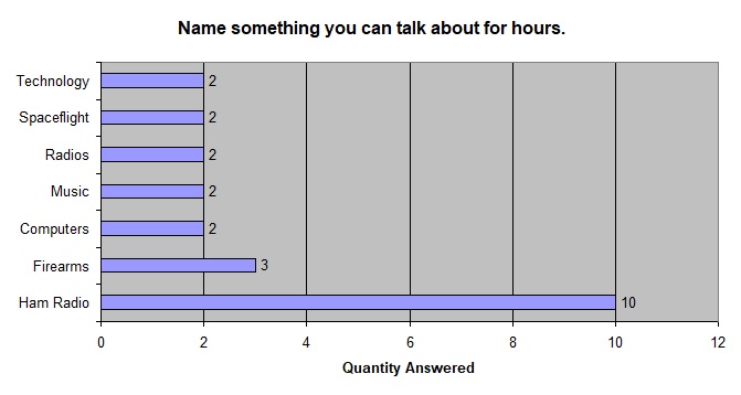 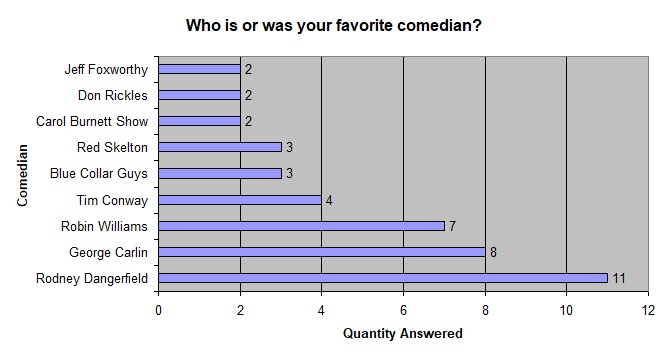 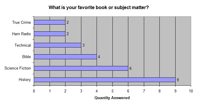 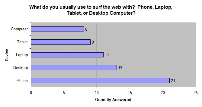 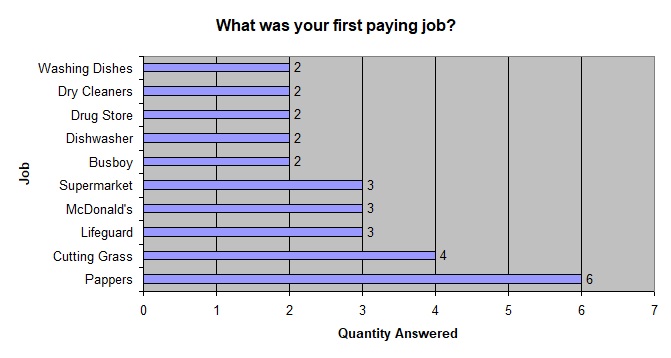  ECR BIRTHDAYS The following hams are celebrating a birthday over the next two weeks. Happy Birthday to you all! K2JPZ, Joe of Leesburg, FL, has a birthday on Monday April 18th KD2UQK, Rob of Deer Park NY, has a birthday on Wednesday April 20th K2CMT, Mike of Debary FL, has a birthday on Saturday April 23rd KD7US, Ron of Cornelius OR, has a birthday on Saturday April 23rd KN2R, Paul of North Fort Myers, FL, has a birthday on Wednesday, April 27th K2SHF, Michael of Port Jefferson, NY, has a birthday on Sunday, May 1st KO4UYJ, Caleb of Milton, FL, has a birthday on Sunday, May 1st KB1ZEB, Larry of Essex Junction, VT, has a birthday on Sunday, May 1st  THE ANTENNA FARM - By Charles KC6UFM Part 3 – Lines and Loads Hello ECR Family, and welcome to The Antenna Farm. This is your friendly Antenna Farmer Charles, KC6UFM. In this article, we’re going to have a look at feed lines and the loads that love them, so let’s get right to it! Feed Lines There is little doubt that having an efficient antenna and feed line system is far and away the most cost effective way of improving your signal. Sadly, many Hams, both beginners and old timers, don’t believe this and instead will go for increased power at the transmitter. The general rule of thumb is that adding power for a given increase in signal costs about 5 times more than getting the same gain through antenna and feed line changes. In practical terms, a system that works “OK” can be made to work “Great” by proper attention to the feed line. The QRP enthusiasts prove this every day by working the world on less than 5 watts of RF...they pay close attention to the antenna gain and feed line loss. Getting your signal to the antenna is one of the most misunderstood things in Ham radio, and I think I know why...people tend to overthink feed lines. It really is simplicity itself. A feed line has the task of getting your signal from the transmitter to the antenna. That’s all it has to do. Those of us with mathematical, physics, and engineering backgrounds will be fascinated by the interactions of frequency, resistance, impedance, and other traits common to feed lines, but for the average Ham, these are details that can actually be safely ignored in most cases. In a practical sense, all you really need to know is that all feed lines have three important properties: Loss – Sadly, all feed lines have a certain loss that varies by length, frequency, and vSWR on the line. There are other factors, but these are the biggies. Some of this loss is due to the resistance of the conductors, some from the reactive components, and some from the actual construction of the line. As either the length, frequency of the applied signal, or vSWR increases, the loss also increases. This means that a feed line that works great at HF (below 30 MHz) with a low vSWR might waste 90% or more of your signal at UHF with a poor vSWR. The loss of various feed lines also varies based on the design and construction. As a general rule, the larger the size of the feed line, the less loss it will have at a given length and frequency, but there are more details and that means these are just rules of thumb. A handy place to look this up is on the web at: https://kv5r.com/ham-radio/coax-loss-calculator/ where you can easily compare the loss of various common feed lines under various conditions. The calculator allows you to vary individual items to see the effect of possible changes. Characteristic Impedance – In absolute terms, you can feed any antenna with any feed line. That’s right...if I wanted to, I could feed a ¼ wave ground plane (about 50 ohms unbalanced) from my transmitter (also about 50 ohms unbalanced) using 450 ohm balanced line. No problem, but there are a few hoops to jump through. It’s much easier to feed the above antenna with an “unbalanced” line that is close to the same impedance. Coaxial cable (what most Hams use) is an unbalanced line that is readily available in ~50 or ~75 ohms. It’s also easy to work with, is relatively cheap, holds up well, and gets the job done. As hinted, there is also open wire line, sometimes called “ladder line”, that has a much higher impedance (usually 300, 450, or 600 ohms), is a “balanced” line, and much lower loss (see the above web site). That whole balanced and unbalanced thing? Don’t worry about it right now...that’s coming in another article. Velocity Factor – This an expression of the speed at which signals move through the conductors of the feed line and is given as either a percent (like 80%) or a decimal (0.80). A VF of 1.0 or 100% means the signal travels through the line at the same speed as in a vacuum, and that is the speed of light (roughly 300,000 kilometers per second or 186,000 miles per second). Knowing the VF of a feed line is really only important when designing lengths of feed line to use as matching transformers or phasing harnesses. Both of these will be covered in later articles. But be warned that even single wires have a VF that, sometimes, needs to be taken into consideration. And do NOT overlook the connectors! I have seen feed lines as short as 10’ made from good quality cable with a measured loss of 15 dB because the connectors were poor quality, installed wrong, or both. Usually both. We’re going to talk more about connectors later, but for now I’ll say that N-type connectors just ain’t all that. Yeah...I’m going to get flack for that, too. I can’t overstate the importance of your feed line...it can make or break your Ham station. You can have the very best antenna possible and 1500 watts of RF output, but if you have 15 dB of loss in your feed line, your signal will be poor at best. Loads Your antenna is nothing more than an electrical load, just like a light bulb. In fact, there was a time when light bulbs were used as antennas, but that’s another story. Again, it’s usually easiest to match the impedance of the antenna, feed line, and signal source (your transmitter), but there are other, more advanced, ways of making this all work. For now, however, we’re going to stick to the simple, easy solutions that work. One word of warning, however...just because WA1BCD has a Super-Whiz-Bang antenna and he can work South Africa on 70cm using 10 milliwatts, that doesn’t mean you can get identical results. There are huge numbers of variables that figure into how a given antenna system will perform at a given location. We’re talking about things like mounting height, quality of the ground system, the very dirt itself, physical things in the environment (like mountains and trees), feed line length, and many, many more. None of that “your mileage may vary” nonsense...your mileage WILL vary. As an aside (and a teaser for a future article), there is one school of thought in physics that looks at an antenna as a matching network...it matches the impedance of the generator (transmitter) and feed line to the impedance of the air. Now, before your head explodes, don’t get all wrapped up around the axle on this right now. One of the most fun things about antennas is that you can make your own. (True...you can make your own feed line, too, but it’s not fun and usually not worth the effort.) This can vary from very simple (like we’ll look at in a moment) to extremely complex. General performance will also vary as the simpler antennas tend to be small, compact, and of “Unity Gain”, that is, they have about the same gain as a ½ wave dipole, or 0 dBd. At the other end of the spectrum (again, no pun intended) are the very complex antennas that tend to be large, spread out, and have gains measured in double digits. This simple antenna has the advantage of being “Unbalanced” and that means you can easily feed it directly with an unbalanced line like coax. No need for baluns, ununs, or other things with funny names. One thing that you will need is to create a “choke” to stop any of your signal from radiating from the coax shield. All that means is to take some kind of form about 4” in diameter (not too critical...I use oatmeal canisters but PVC pipe works well, too) and wrap the coax feed line around the form 5 or 6 times. Tape or glue the coax in place. This choke should be located within about 2 feet of the antenna feed point. You can do the same thing with a few ferrite beads on the coax near the feed point. In most cases, having a choke on your feed line will not hurt anything, but some designs (like an end-fed half wave) will not work right with a choke. Again, in most cases, it might not help, but it won’t hurt. In the case of a ¼ wave ground plane, the choke is a huge help. 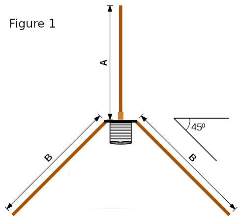 ¼ Wave Ground Plane (Figure 1) Let’s look at one of the simplest things you can build, and that is the ¼ Wave Ground Plane. The parts list comes down to a single SO-239 panel mount UHF coax socket, four 4-40 machine screws about ½” long, four 4-40 nuts, twelve #4 flat washers, and some #10 or #12 AWG bare solid copper wire. The only tools you will need are a screwdriver for the machine screws, a wrench for the nuts, a pair of needle-nose pliers, an SWR meter for the desired band, and a soldering iron. This little antenna is effectively a ½ wave dipole where each element is about ¼ wave long mounted to give vertical operation (for now, don’t worry about horizontal and vertical polarization) that is perfect for working local repeaters on VHF and UHF. See Figure 1 for the details. You will cut some wire to the correct lengths, attach the four longer wires to the SO-239 using the #4 hardware, bend those radials down to about a 45 degree angle (keep them all as close to the same as you can), and then solder the remaining short wire into the center pin of the SO-239. A little dab of silicon rubber caulk on the soldered joint and connector insulation will keep rain out of the coax and connector. The approximate dimensions for the wires are: 2m (146 MHz) A = 19-1/4” B = 21-1/2” (four of these) 1.25m (224 MHz) A = 12-1/2” B = 14” (four of these) 70cm (445 MHz) A = 6-1/4” B = 7” (four of these) Personally, I always cut the wire a little long and then trim them back as I tune the antenna as described below. Using an SWR meter check the vSWR. This antenna, when adjusted for the center of the band, should cover the entire 2m and 1.25m bands, and the upper 10 MHz of the 70cm band (the FM portion). If you wish to shift the resonant frequency, adjust the length of the upright element where longer will shift lower in frequency and shorter will be higher. Make VERY small adjustments to the length! The match should show close to 50 ohms, but you can adjust the antenna impedance by adjusting the angle of the radials...less than 45 degrees will be lower and greater than 45 degrees will be higher. Again, if you adjust the “droop” of the radials, try to keep all four the same. As you can see, this is a very compact antenna...even the 2m variant is only about 3’ tall. You will have to work out a way to mount the antenna, but when I’ve built these in the past, I’ve done a little bit of everything including (but not limited to): Using a hose clamp around the PL-259 coax connector to strap the whole thing to a wooden dowel; Gluing the SO-239 to the end of a PVC pipe and running the coax down through the pipe; Using silicon sealant to glue it to something; Putting a small loop at the tip of the upright element and using a string to hang it all from a tree limb...I’m sure you can get creative! When mounting the antenna, keep in mind that ground plane antennas work best when at least two wavelengths above ground. For 2m, this would be about 7’ minimum, and, in general. VHF/UHF antennas should be mounted as high as possible. While I don’t think I would try it with the 2m version, the 1.25m and 70cm versions could be taken mobile with a little thought. I have even seen Hams with the 70cm version mounted to a hat and connected to their HT as they walk around Ham Fests and such. As mentioned, this antenna is a unity gain system, but if you are using a handheld radio, this will have as much as 27 dB gain over your rubber duck antenna. Even compared to the high-end HT antennas, you’re still looking at gains in the 3 dB range. And remember that a 3 dB gain is doubling your signal. There are many good sites online for calculating the dimensions of quarter wave ground plane antennas. My favorite is: https://m0ukd.com/calculators/quarter-wave-ground-plane-antenna-calculator/ where you can input your exact desired frequency. This is the site used for this article. If you do this, remember that you should enter the center of the desired frequency range. In theory, that will be the point of lowest vSWR and as you move higher or lower in frequency, the vSWR will rise. Next time, we’ll take a look at the mysterious, and often misused, Standing Wave Ratio. Take Care & 73 de KC6UFM Charles NEW REPEATERS ON THE ECR - By Dick WB2JPQ Thanks to Matt, N2YCK, we have three new repeaters on the ECR system severing the Rochester area. The repeaters are located on a hill in the town of Rush, NY, which is south of Rochester. The repeaters are as follows: 145.350 -0.6MHz 110.9Hz 224.020 -1.6MHz 110.9Hz 443.750 +5MHz 110.9Hz Hopefully we can get the word out to our Rochester users that have not had access since 146.790 went down last November. A FEW WORDS ABOUT VINTAGE EQUIPMENT - By Henry WB4IVB I have begun a restoration project on a 1950's vintage Seeburg Jukebox. I have had it in my possession since 1987. I thought someday I would "get-around-to-it", but that day has just arrived. This unit was the first "Stereophonic" model produced by Seeburg. The audio amplifier is tube type, two channel, with a common power supply. There are several more electrical components including the “Tormat Selector” which is also tube type. But, for now, I am concentrating on the audio amplifier. After removing the audio amplifier, a quick peak at the under chassis If you ever purchase any vintage equipment at a hamfest, whether it be a receiver, transceiver, amplifier, or whatever, you need to be very cautious before coming home and plugging in. I highly recommend a complete inspection of the components prior to powering-up. Even after a visual inspection, I recommend bringing the AC line voltage gradually with a Variac. If the equipment has Paper or Wax Capacitors it will probably Remember, capacitors Block DC and Pass AC. Bad electrolytic (polarized) capacitors have a tendency to break down and explode if the insulation material has broken down internally. So, as I change capacitors in the Seeburg audio amplifier I only have to be concerned with “polarity” on the electrolytic type you might think. Absolutely not, even non-electrolytic type capacitors can be Many modern capacitors of today, unless they are polarized, have no markings other than the value and voltage. A good example is the “Orange Drop” or “Brown Drop” capacitors. Even though you cannot see it because of the construction of these capacitors, these type capacitors have a foil as an external layer. This foil runs the entire length of the capacitor body. These are great for audio, but the “foil connection end” needs to be connected to the chassis, or low impedance point. This ensures the best performance by “shielding” the circuit from undue noise or hum. I have found several of the orange-drop capacitors that had a black line as a mark, but unfortunately it did not indicate the foil Henry WB4IVB  YACHT NEWS for April 16, 2022 - By Captain Ed KG8CX Young Amateurs Communications Ham Team, K8KDZ, Sailing Over Radio Waves Connecting Young Hams, Creating Friendships, Expanding the Voice of Youth in Ham Radio Inspiring Youth with Enjoyment & Technology of Ham Radio ------------------------------------------------------------------------ Keep in touch with us on Facebook, YACHT chats, YACHT youth net, YACHT News ------------------------------------------------------------------------ NET REVIEW... Good youth net on Saturday. Following youth connected: YS1YXI, 2W0KYH, N8JJM, K0NNK, K0EFW, KC3OTG, KE8RJU, KD9RTI, KJ7MFU, KJ7MPQ, KN4VKW, KN4VKY, KE0ZNV, KE8TJU, WS8EMT, KE8LQR. Also thanks to others who checked in. All are appreciated even all we see is your call on screen. CHAT SESSIONS... Monday: 14 connections including these youth, N8JJM, KE8MPK, KI5JXQ, KE8RJU, KE8LQR, KO4ZED our newest youth member, KI5QBQ. Tuesday: **SPECIAL NOTE** Due to our local ham club meeting on Thursday evening, I will not be available to run the chat session. Katie KE8LQR will run the chat session in my place. Thank you Katie. SPECIAL OPPORTUNITY FOR YOUTH HAMS... This message was sent to me by Oscar Wood 2E1HWE. It involves a net for young hams on Easter Sunday April 17. Here is the page and you will note that Echolink is available #722751 along with other digital modes. Times are 9am to 11am CDST. Adjust for your time zone. [link] *Declan's dad GW8SZL will link the Freestar network to the YACHT node for the 2 hour youth session, so if you have some time and are interested, go to our echolink node and check in. Declan 2W0KYH will run the first hour... Times are 9 to 11am CDST Sunday the 17th Here is Oscar's personal email to me... "Hi Ed, A fellow Ham & friend Dave Roberts “GW8SZL“ gave me your contact details as we would like to invite you and your members to be guests on a special worldwide Easter Sunday pop up net that I have arranging for young hams of all license grades under the age of 25. Declan 2W0KYH will be the net controller for the first hour. Please do let me know if you can join us as a special guest to briefly talk about YATCH?" And here is the official page [link] BIRTHDAY GREETINGS TO... Katie KE8LQR on April 18. Also to Timothy KC3CDU and James KC3CDV. OHIO YOUTH NET... The first Ohio section youth net went online Sunday evening at 7:30pm EDST with Katie KE8LQR as net control. She had 14 check ins. The net will again be held the 2nd Sunday of each month. May 8 is the next one. NEW MEMBER WELCOME... We now add our newest youth member, Chris Torres KO4ZED #401. He recently passed the Technician exam along with his Mom and Dad. He is our 24th new youth member this year. With 8 new adult members, our count for 2022 is 32 added. SPECIAL CAR... You've got to see this, unbelievable: [link] WORLD AMATEUR RADIO DAY... Mark this date and make your effort to promote ham radio and YACHT [link] One of the net controls for the Roc-Ham system is Declan 2W0KYH. Here is a post on their operation ... [link] Scroll down to the "VOIP, Roc-Ham" segment for the echolink and other modes. Declan will be running N.C. from 9 to 11am CDST. *Here is the complete information on World Amateur Radio Day and where to connect [link] VOIP/ECHOLINK *ROC-HAM* Conference node #531091 18 – 19 April 13:00 — 04:00 UTC (9AM EDT-1AM EDT) via VOIP/ECHOLINK *ROC-HAM* Conference node #531091/Allstar #2585,47620, 53130, 53131. W2JLD, GW8SZL, 2W0KYH, VA3ODJ, KI50ZZ, KC5FM, GM0UUB, KD2GUT, KL7RCS Net Controllers. Special event callsign W2W. All stations from around the world are encouraged to check in. Special event qsl Card will be available via S.A.S.E. for more info goto www.roc-ham.net HIGH ALTITUDE BALLOON VIDEO... Watch the latest balloon venture from Audrey KM4BUN and Jack KM4ZIA Click on the link for an interesting tour of preparations for their latest launch: "Hi folks, This is our latest family video: https://photos.app.goo.gl/yazFgTLxGMpABxH79 Turn up the speakers, you'll hear lots of good music. The topic will be one that you'd expect from us! 73 Tom and Janet McElroy" -- 73, Ed Engleman KG8CX http://yacht.younghams.org/ http://yachthams.webstarts.com/index.html http://w8pif.webstarts.com/index.html http://www.qrz.com/db/k8kdz WE NEED SOMEBODY TO DO INTERVIEWS! - By Michael K2SHF We are looking for someone to interview members of our ECR family with Q&A sessions. This would be done via email, telephone, or even Zoom. We are looking for an interview to be done every 1-4 weeks. The frequency of interviews can vary based on your availability. The interviews will be published in our newsletter. We've done two interviews in the past... WB2JPQ and KO4QMM. They came out great and were interesting to read. We would like to see more interviews for our newsletter. If you have any interest in this project, please email me at k2shf(at)arrl(dot)net for more information. |
| FACILITATORS Dick WB2JPQ Henry WB4IVB Emil WA2UPK Bob KB3SNM Tony W2KJV Kevin VE3BZ Paul W4END David KB4FXC Kevin KE7K Joe KO4FRR Mike K2CMT Michael K2SHF Steve K2EJ Keynon KB5GLC Dan KD2VNU |
ECR ACCESS IRLP 9050 AllStar 27339, 45192, 45225 Echolink WB2JPQ-R(57780), WB2JPQ-L(375103) DMR Brandmeister 3129973 DMR TGIF 9050 System Fusion 44444, 92805 DStar XRF(XLX)256E HamShack Hotline 94049 P25 31582, 9050 M17 M17-ECR Module A NETS Tech Net Tuesdays 8PM ET Morning Brew Mon-Fri 7AM ET YACHT Youth Net Wednesdays 8PM ET |
WEBPAGE http://eastcoastreflector.com ZOOM ROOM Open 24/7. All are welcome! ID: 83929643320 Password: 193414 http://bit.ly/ecrdaily MERCH SHOP http://bit.ly/ecrshop TECH NET LOG http://bit.ly/ecrtechnet YOUTUBE CHANNEL http://bit.ly/ecrYouTube |