
| Newsletter
Home | ECR Homepage |
ECR Shop
| ECR
YouTube | ECR
Groups.io | ECR Facebook |
July 18, 2022
 MORNING BREW Q&A - By Michael K2SHF Thank you to all who checked in to the Morning Brew. The following are answers to some of our recent daily questions. We asked the following questions. As always, only answers with a tally of 2 or more were included below. Thanks to Derby Dan (KD2VNU) for his hard work in logging the answers and tallying the results after each net. 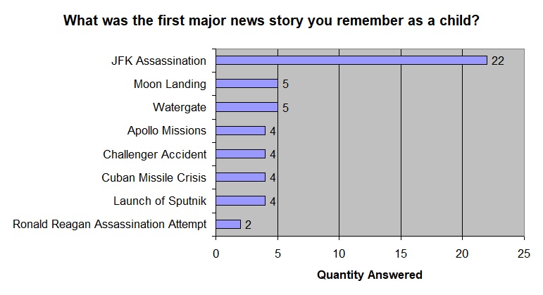 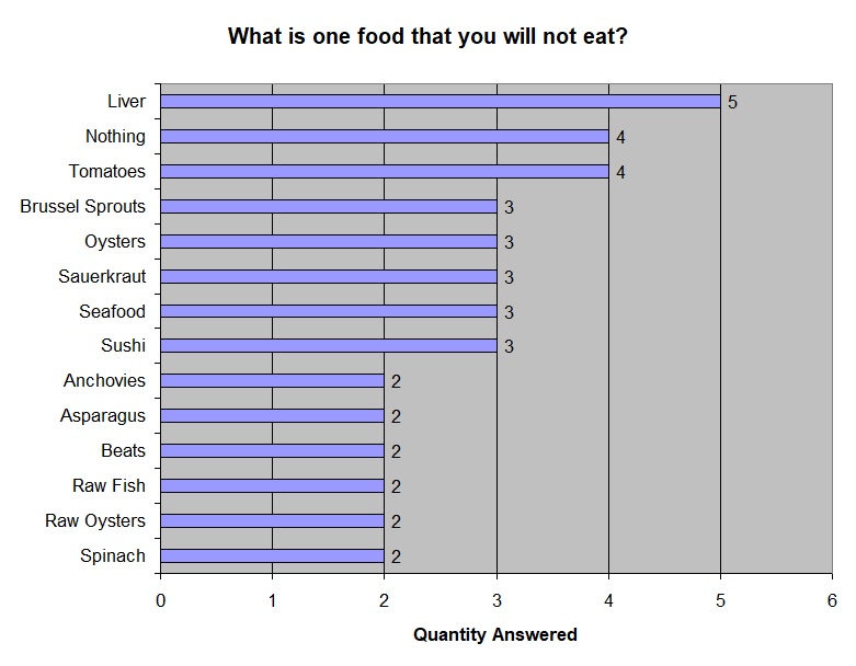 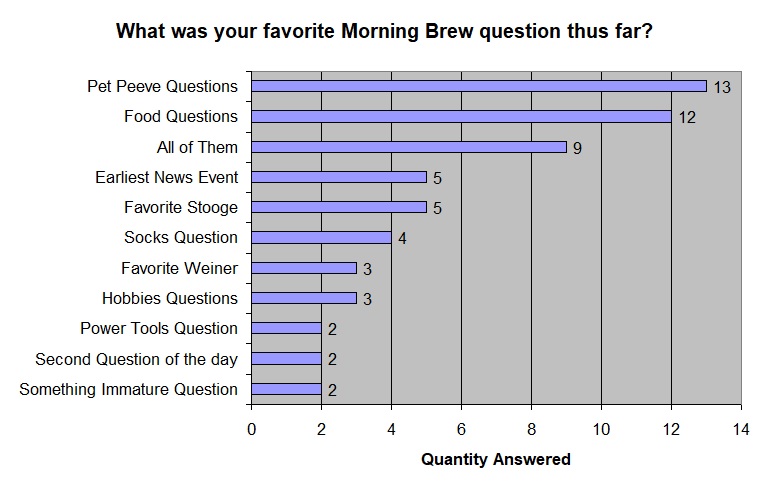 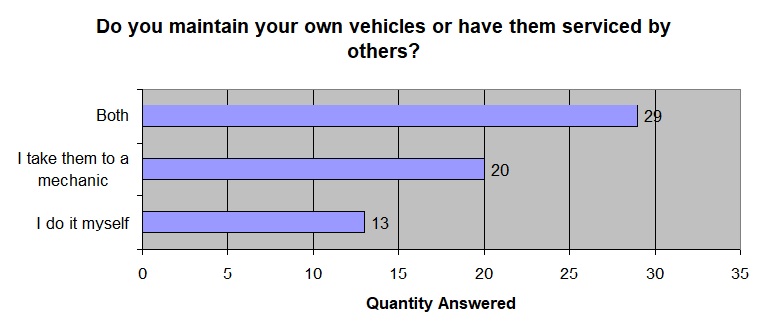  ECR BIRTHDAYS The following hams are celebrating a birthday over the next week. Happy Birthday to you all! N7WZI, Alan of Lubbuck TX, has a birthday on Tuesday, July 19th N9AIM, Bob of Brownsburg IN, has a birthday on Thursday, July 21st KO4DKN, David of Boynton Beach FL, has a birthday on Sunday, July 24th Would you like your birthday recognized in the Newsletter and on the air during the Tech Net? Just send an email to Michael, K2SHF, with your callsign and birthdate. Your birthday will then be added to our spreadsheet.  THE ANTENNA FARM - By Charles KC6UFM Part 9 – Impedance Matching Hello ECR Family, and welcome to The Antenna Farm. This is your friendly Antenna Farmer Charles, KC6UFM. Remember way back in Article 4 on SWR we talked about the simple fact that you can get maximum energy transfer from one system (like your feed line) to another system (like your antenna) when the impedances are exactly equal? Actually, we’ve danced around that idea a number of times in the last eight articles, but now we’re going to look at how to make that happen. Most antennas, when tuned to their resonant frequency by adjusting their physical dimensions, will not be anywhere near the characteristic impedance of your feed line. Think back to the simple dipole as an example...a resonant dipole (no matter what the resonant frequency is) will have around 73 ohms of impedance. This is close to the unbalanced coax like RG-59 and a few others that are 75 ohms, but your transmitter likes 50 ohms best. So the problem becomes matching, somehow, that 50 ohm RG8 coax to your 73 ohm antenna. The most common solution that the majority of hams will use is an Antenna Matching Unit, usually wrongly called an “Antenna Tuner,” to get a nice, low SWR at the radio. Again, as stated in Article 4, an antenna tuner (hereafter called an ATU) does NOT tune the antenna. You can only tune an antenna by changing its physical properties. The ATU just makes your transmitter happy. This all may seem like a big problem, but it’s all in how you look at it. I see these variable impedances as a gift, an opportunity to do some amazing things. To understand why I see this matter in the way I do, we’ll need to look first at how to match two different values of impedance to get maximum energy transfer. So grab your shovel and let’s dig in! General Concepts Impedance matching applies to far more in electronics in general than just antenna systems. While far beyond the scope of The Antenna Farm, impedance matching is used inside your transmitter and receiver to connect the various stages of the rig to each other. This is because of the fact that maximum energy transfer happens only when the output of one stage is matched to the input of the next stage. The “Alignment” of a transmitter or receiver is mostly a process of matching the impedance of the various stages. The important thing to remember—and I know I’ve said this a lot—is that the goal is maximum energy transfer, and that only happens when the impedance of the two subsystems are exactly the same. Next, remember that impedance is just the opposition to current flow in an alternating current (AC) circuit that is made up of resistance and reactance. In a true direct current (DC) system, there is no reactance, so we only need look at the resistance. The values that we are concerned with are usually represented in equations as: Z = Impedance in Ohms X = Reactance in Ohms R = Resistance in Ohms Reactance has two sub-types: Xc = Capacitive Reactance in Ohms Xl = Inductive Reactance in Ohms Further, reactance lives in the mathematical realm of “Imaginary Numbers.” I know this sounds overwhelming, but stay with me here...it isn’t that complicated! If I ask you to tell me the square root of 9, most people know that the correct answer is 3. This is because 3 * 3 = 9. No problem! But if I ask you for the square root of -9 (negative 9), most people also know that this is not defined...there is no number that, when multiplied by itself, will give the result of -9. Go ahead, try it...3 * 3 = 9 and -3 * -3 = 9! So, purely to make the math work, we use imaginary numbers. An imaginary number is nothing more than a “real” number that has been multiplied by a value we call “i” that is defined as the square root of -1. To identify an imaginary number, we prefix it with the letter “j” so the square root of -9 would be written as “j3.” What this whole imaginary number deal does for us is to allow manipulation of the reactance using regular arithmetic. And just in case you’re wondering, there is a way to deal with this using calculus and trigonometry. You probably weren’t wondering, though. By convention, we call inductive reactance positive and capacitive reactance negative. This means that if we have a circuit with 1 ohm of resistance, 1 ohm of inductive reactance, and -1 ohm of capacitive reactance, the total impedance becomes 1 ohm. The solution would look like this: Z = R + Xl + Xc Z = 1 +1 +(-1) Z = 1 Impedance is usually written without doing the addition of R and X so we can see what the reactive part is. That notation looks like: Z = R (+/-)jX The “(+/-)” bit is set to reflect if the reactance is more inductive (+) or capacitive (-), The “j” tells us that what follows is an imaginary number, and the “X” is the final, absolute value of the reactance in ohms. So, if you’re designing an antenna in EZNEC you will see the feed point impedance of the antenna on the screen. It will be in the form above. If you were to see something like Z = 35 + (-j18), that means your antenna’s feed point will present 35 ohms of resistance and 18 ohms of capacitive reactance. Ideally, you will normally want a value here that has no reactance. That is, in most cases, not a reachable goal. Almost all antennas will present at least a little reactance. Small amounts aren’t usually a problem, but large values need adjustment. This is all well and good, but just what is reactance in the first place? I’ll be asking you to think back to your exams for Technician, General, and Extra class licenses. All three cover reactance to some degree. Again, reactance is simply the opposition to current flow in an AC circuit. There are two equations, one each for inductive and capacitive reactance. They are: Eq. 1 Xl = 2 * π * F * L Eq. 2 Xc = 1 / ( 2 * π * F * C ) where: Xl = Inductive Reactance in Ohms Xc = Capacitive Reactance in Ohms F = Frequency in Hertz L = Inductance in Henries C = Capacitance in Farads π = 3.14 Now, please gather up the pieces of your exploded head...it’s staining the carpet. There are two websites to make this easier: For Capacitive Reactance, use: https://www.omnicalculator.com/physics/capacitive-reactance For Inductive Reactance, use: https://www.omnicalculator.com/physics/inductive-reactance If you go to these two sites and play with the calculators, you’ll find that inductive and capacitive reactance behaves differently as you shift the frequency up and down...assuming you leave the inductance alone, as frequency increases, inductive reactance increases. By the same token, as you increase frequency, capacitive reactance decreases. This is why we assign a negative value to capacitive reactance and a positive value to inductive reactance. This also means that if your antenna is, let’s say, capacitive, you can cancel this by adding in some inductance. If we use the value we got from EZNEC above ( Z = 35 + (-j18) ) we could add 18 ohms of inductive reactance to get a pure resistance of 35 ohms. All we would need to do is calculate how much inductance to add to get the needed reactance. There is one huge fact that comes to our rescue from doing all this math… Any antenna, at resonance, will present a purely resistive (that is, non-reactive) load. This applies ONLY to the exact resonant frequency. As you move from resonant to a higher frequency, the load begins to show more inductive reactance. As you move lower in frequency, the antenna becomes more capacitive. The rate of change depends on the exact design/type of antenna, but it may be fairly slow or it could end up changing very quickly. This is why as you move away from your antenna’s design frequency, the SWR goes up. No matter if the antenna is capacitive or inductive, the overall impedance is moving away from the “sweet spot” of resonance, and so the match falls apart. This is why we need to match the antenna, feed line, and generator as a system. Matching Techniques You’ll be glad to know that we’re done with the math. Well, for now, anyway. There are many different ways to match your antenna, feed line, and transmitter, but only a few that are popular. We’re going to take a look some of those now. 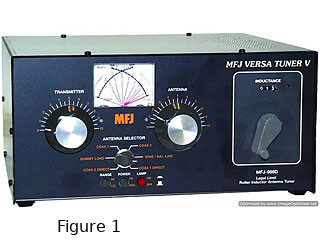 The Antenna Tuner (see Figure 1) Again, strictly speaking, there is no such thing as an antenna tuner. Be that as it may, we’re going to use that name because that is what everyone—wrongly—calls them. Often just abbreviated to ATU (Antenna Tuning Unit), pretty much everyone has seen them. Essentially there are two types called Automatic and Manual. You can probably guess the difference...the automatic ATU will make the needed adjustments when you key your transmitter while the manual ATU requires you to turn a few knobs. Within each type, there are two basic sub-types: Local and Remote. The local (you will only rarely see this name used) is located at the transmitter, usually connected with a very short feed line jumper (this is what Figure 1 shows), while the remote type mounts at the antenna location. The real job of the ATU is make the antenna appear to be a pure resistive load to keep the transmitter circuits happy. Too much of a deviation from a pure 50 ohm resistance will, eventually, damage your transmitter, and the ATU adds the needed inductance and capacitance to cancel out the reactance of the antenna and try to find someplace where the resistance is near 50 ohms. It is very important to remember that the ATU does NOT tune your antenna to resonance. If your antenna is so far from resonance that it is failing to put out a good signal, the ATU can’t fix that. It may, however, let your transmitter think the antenna is perfect. It’s not. That doesn’t mean that an ATU is never needed...let’s say you have a simple wire dipole cut to resonate at 52 MHz. At the resonant frequency, the SWR will be near 1:1, but if you move to, say, 50.05 MHz, the SWR could easily be 5:1, more than enough to damage your rig. The antenna in this example will likely be fairly efficient at 50.05 MHz, but your radio will also go belly up fairly soon. An ATU would allow you to “tune” the system so your rig will be safe and you can still use the antenna. Many newer radios, particularly the so-called “Shack-In-A-Box” styles, have a built in ATU. In most cases, these built in ATUs aren’t able to match anything larger than about a 3:1 SWR. Most external ATUs, both local and remote, can handle up to around a 10:1 SWR, some even higher. Many local, external ATUs also have the ability to match coax, open wire, and even single random wire antennas. But inside, all ATUs are the same...they have some sort of variable inductor and variable capacitors. Top of the line units often have a “roller inductor” that is continuously variable from 0 to some high number for the inductance. Better units use special variable capacitors, often so-called “vacuum variables” that are pretty pricey. Less expensive ATUs and all internal ATUs use fixed value inductors and capacitors that are selected by relays or switches. Again, the idea is to get the overall impedance as close to (typically) 50 ohms and as non-reactive as possible. Since the ATU has no resistors in it, the ATU will add small amounts to reactance as needed to get the impedance close to 50 ohms. This is important...just because the ATU gets you to 1:1 SWR, that does not mean things are perfect. It only means that your radio will probably not cook itself. Maybe. Remember, your SWR meter can’t show you reactance, and it sees only overall impedance. In some cases, the ATU will need to add so much reactance to get the overall impedance to something that looks close to 50 ohms that you will see a 1:1 SWR while the radio finals are seeing something very different, sometimes different enough to overload your rig. Most hams will get an ATU at some point, and that’s just fine. They are very useful for antennas that are fairly narrow-banded (like a wire dipole) to allow you to work across the band on a single antenna. With that said, there is a difference in how local and remote ATUs will work for you… A local ATU will leave the high SWR of the antenna to appear on the entire length of the feed line. As you know, high SWR on the feed line will increase feed line losses, and this could eat up more of your valuable signal on both transmit and receive. On the other hand, a remote ATU connects as close to the antenna as possible, so not only does your radio see a good SWR, but the feed line also sees a low level, so the loses are minimized. It’s a trade off…as a rule, local ATUs are less effective, easier to install, and cheaper. Remote ATUs are more efficient, more expensive, and harder to install. You’ll have to decide what works best for you and your system. 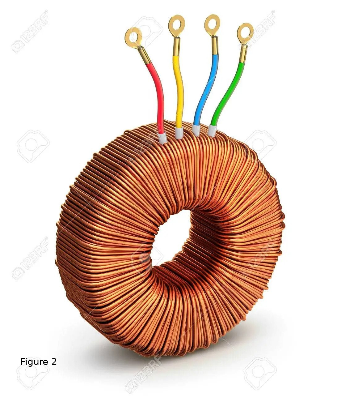 Matching Transformers (see Figure 2) There are many types of transformer based matching systems because there are many types of transformers. While most RF transformers today use toroidal cores, there is no reason why you can’t use rod cores, E cores (traditional power supply type), or others. It is theoretically possible, but there are some issues we’ll look at in a minute. The old timers out there will remember the “IF Cans” used in years gone by to match receiver stages. These were just small coils of wire enclosed in a metal “can” with an adjustable core. There were, like in all transformers, at least two coils and you could vary the impedance by moving the core, or “slug,” in and out of the windings. In more modern times, especially with antennas, you will more commonly see “Toroidal” transformers as shown in Figure 2. I know...here we go with the funny names again! A toroidal core looks like a doughnut or a ring. The windings making up the coils are looped through the center hole and around the doughnut. There are two big advantages to a toroidal transformer, and those are that the transformer can be made smaller (and space is always at a premium) and the magnetic lines of force are almost totally contained within the torus (boosting efficiency and reducing interference). Yes...I can hear you. “What’s this magnetic lines of force deal??” A transformer works because when you pass a current through a conductor (like a wire), a magnetic field is created around the wire. Inversely, if you pass a magnetic field over a conductor, there will be a voltage created in the wire. No, we are not violating conservation of energy here...we are transferring energy from one coil winding to another coil winding using magnetic lines of force. All transformers have loss, that is, if you put energy into one winding (called the Primary), you will not get the same energy from the other coil (called the Secondary). Some energy will be lost, mostly as heat. The more of the magnetic lines of force coming from the primary that “cut” across the secondary, the less loss you will have. In a toroidal transformer, almost all of the primary lines of force cut across the secondary. Now, here comes the neat part… A transformer can change the energy around. No, the transformer can’t create or destroy the energy, but it can modify the energy. The transformer deals with energy, and for our uses, that energy is the voltage and current in the primary and secondary circuits. Let’s say that the primary circuit delivers 100 volts at 1 amp to the transformer. Using Ohm’s Law, we can find that this comes to 100 watts (100V * 1A = 100W) and that the impedance of the primary coil is 100 ohms (100V / 1A = 100 ohms). Let’s say that the wire we used to make the primary winding needed 100 turns to get the needed 100 ohms. Now, we want to get 50 volts out of the transformer on the secondary side. Remember, we can’t create or destroy energy, and for this case we will assume that there are no losses. The total energy is, as you recall, 100 watts, so we can use Ohm’s Law to find that the current on the secondary will be 2 amps (100W / 50V = 2A) and that the impedance of the secondary will be 25 ohms ((50V * 50V) / 100W = 25 ohms). Theoretically, the ratio between the number of turns of wire will be 2:1, that is, the secondary will have only 50 turns. The above example is called a “step down” transformer when used in power circuits because it steps down 100 volts to 50 volts. But we don’t care about that… What matters for us in antenna work is the fact that we get 100 watts of power from a 100 ohm input to a 25 ohm output. Disregarding losses, we just did an impedance transformation. While I wanted to show you the above example using the simple arithmetic of Ohm’s Law, there is a fairly easy equation to reach the same conclusion… Eq. 3 Turns Ratio = √(source impedance/load impedance) Using the impedances from our example, you get: TR = √(100/25) = √4 = 2 But now you know where this magic equation came from. While there are some exceptions, almost all impedance transformers used with antennas are toroidal, and within that family, there are many variants. In addition to impedance matching, you can also convert between balanced and unbalanced systems. Often, there will be both balun and impedance matching functions going on at the same time. To further muddy the waters, there are many ways to place the windings on the toroidal core, and each has its advantages and problems. And just to add to the general fun, the toroidal cores come in a wide range of sizes and compositions. By composition, we are talking about the actual material used to make the core. At one end, we have the simple iron cores that are nothing more than iron filings mixed with an epoxy resin and molded into shape. At the other end we have so-called “ferrite” cores that are made from iron plus other metals in very precise amounts. Some military grade cores use very esoteric blends and are cast into ceramics. These different materials have been more or less standardized and we call them “Mixes.” The difference comes down to how much of a magnetic field the core can survive, the maximum temperature the core can handle, and the frequency range the core is effective over. The selection of a proper mix for a given transformer design can be complex, and it is beyond the scope of this particular article to teach you how to do that. If, for now, you would like to see a sample of the properties of various mixes, have a look at: https://www.fair-rite.com/materials/ The biggest advantage to transformer matching system is that they can be made to cover a quite large bandwidth. Units that cover from 160m to 6m are very common. The price for this frequency agility is that transformers—even toroidal—have a fairly high loss, and that loss is seen as heat. In practice, the biggest thing you need to watch for is overheating the toroidal core. In your shack, this will show up as a sudden, usually radical, change in your SWR. Remember when I told you that an SWR meter actually is worth the money? This is why! If this sudden change occurs, one of two things has happened: The core has overheated and/or reached saturation, or, The core has REALLY overheated and cracked. If the former, just shut down, wait a while as the core cools, and try again with lower power. In the case of the later, buy or build a new transformer. In a future article, we will go into the details as we build a balun to match to a dipole. Feed Line Matching Systems This group is, far and away, my personal favorite because we can use a length of feed line to match our length of feed line to our antenna. Don’t give me that, “What you talkin’ ‘bout, Willis?” look! Feed lines in particular lengths have some interesting properties. Again, here, we’ll look at two extremes and then extrapolate to see other cases. Take a length of feed line that is ¼ wave long at some frequency. There are two special cases we can see right away… 1) The far end of the feed line is left open. In this case, the impedance at the near end will appear very low. 2) The far end of the feed line is shorted. In this case, the impedance at the near end will appear very high. This may appear counter intuitive, but it has to do with the interaction between the forward and reflected energy. There will be a future article on the Smith Chart that will make this all perfectly clear. It should be obvious that between a fully open circuit (impedance = infinity) and a fully shorted circuit (impedance = 0), there can be infinite values of impedance at the far end of the line. This also leads to the fact that the near end will also have an infinite range of possible impedances. And this is our friend! Again, we’ll cover all these calculations when we discuss the Smith Chart, but for now, I’ll give you a handy short cut...go to https://www.everythingrf.com/rf-calculators/quarter-wave-transformer-impedance-calculator and you’ll find a handy calculator. You simply enter the two impedances you need to match (usually your antenna’s impedance and your main feed line impedance), this calculator tells you what the impedance of the ¼ wave matching section needs to be. For example, if you want to match a folded dipole (about 292 ohms) to your 50 ohm coax, you’ll need a ¼ wave long section of feed line with 120.8 ohm characteristic impedance. Yes, there is 120 ohm coax. If you like punishment, the equations are also on the page with the calculator. There are a number of popular feed line matching systems that are all based on the concepts presented above. One of the most common is the “Hair Pin Match” where the only difference is that we build a section of open wire feed line, short it at one end (a variation leaves the end open), and then find the point along the hair pin where we get the right impedance. I hope that sounds familiar because this is the exact system that the J-pole uses. Those with at least a passing familiarity with beam antennas may be aware of the Gamma Match. The gamma and similar systems are just modified feed line matches. Many of these specialty feed line matches will be covered in greater detail—including their design, installation, and adjustment—later when we look at specific antennas where they are commonly used. One of the variations on the feed line matches I want to mention here is the “Strip Line” that is used at UHF and higher frequencies. This nothing more than a ¼ wave feed line, but due to the frequencies involved, it is extremely small...so small in fact that it is normally implemented on a printed circuit board (PCB). There is nothing magical or unusual with a strip line. At, let’s say, 10m, a ¼ wave section of feed line will be around 10 feet long. At 23cm, that same ¼ wave will only be around 2 inches long. Try cutting a section of RG8X accurately to be only 2 inches long. Likely won’t happen...the tolerance on the measurement and cut is the thousandths of an inch. So we “build” a feed line on a PCB, and that we can do very accurately. The top advantage of a feed line match is that they are almost outrageously efficient and have very low loss. The downside is that they are, as a group, somewhat narrow in bandwidth. That’s because the match itself is designed and built for exactly one frequency. Using larger diameter elements on the antenna and larger feed lines can mitigate this to a point, but not by very much. There are many other impedance matching systems (like filters and resistive networks), but most are highly specific and not able to be a “Jack Of All Trades” that ham radio usually requires. Plus, few work as well as transformer and feed line matches. So, the question comes down to what I would use. The answer is, sadly, it depends...for instance, just as an easy example, if I have a 6m dipole (I do), I would match it to my coax via a feed line match and then use a remote automatic ATU to get full band coverage. My 6m dipole is tuned to resonate at 50.5 MHz (to cover the data/CW/SSB segments), and the ATU lets my rig (and main feed line) see a low SWR up in the FM portions. As I said, I like feed line matches, but that isn’t the one-size-fits-all solution. On my 40m-6m EFHW, I use a broadband toroidal transformer. This antenna is fed through a local automatic ATU, and my highest SWR on the covered bands WITHOUT the ATU turned on is 2.5:1. With the ATU in the circuit, I see very close to a 1:1 all the way through. Interestingly enough, the antenna will load on 160m-60m with the ATU as well, but it isn’t terribly efficient...it’s just too short for those bands. As with so many things in ham radio, you need to look carefully at exactly what you want to do with your system. Bounce some ideas around with other hams, particularly your Antenna Elmer, and decide what is going best solve your particular problems. Having a good, broad understanding of what is possible and how it all works will make these choices much easier and, more to the point, more likely to accomplish your goals. Finally, why do I, as an antenna designer and builder, see the world of impedance matching as a gift? Because the simple facts we’ve looked at here allow us to connect ANY antenna to ANY feed line, and there is more...one of the biggest and—based on comments and questions I hear on the air—most misunderstood applications of impedance matching is the phased antenna array. In order to make a phased array work the way you want it, the individual antennas must be fed at precise phase angles and with precise current values. By manipulating the impedance and matching of the antennas in the array, we can do this. Or, simply put, we can make a phasing harness. Phased arrays can have very large gains, very low losses, and even be steerable with proper matching. That’s it for this time. In our next trip to the farm, we’re going to look at a single very popular antenna for limited space applications, both because it works very well and because it shows you how to think outside of the box. Oh, and it can cover twelve bands. And should cost about $10 to make...Maybe less. Take Care & 73 de KC6UFM Charles JUST AHEAD IN RADIOSPORT Taken from the ARRL Letter July 18 -- OK1WC Memorial (MWC) (CW) July 18 -- RSGB FT4 Contest (FT4) July 20 -- A1Club AWT (CW) July 20 -- VHF-UHF FT8 Activity Contest (FT8) July 21-22 -- Walk for the Bacon QRP Contest (CW) July 21 -- NAQCC CW Sprint (CW) July 21 -- NTC QSO Party (CW) July 23-28 -- YOTA Contest (CW, phone) Visit the ARRL Contest Calendar for more events and information. HOW CAN YOU HELP OUT WITH THE NEWSLETTER? Looking for inspiring journalists to interview various ECR ham radio operators on a monthly basis for the ECR newsletter. The interview will concentrate on amateur radio related interests. The pay is on the extreme end of low. No paid vacation or medical benefits. If interested please contact Michael K2SHF, Ben K8BWK, Tom KE3GK or Scott W2BLT  YACHT NEWS for July 16, 2022 -- 15th Anniversary Edition -- Young Amateurs Communications Ham Team, K8KDZ Sailing Through Radio Waves Connecting Young Hams, Creating Friendships, Expanding the Voice of Youth in Ham Radio Inspiring Youth with Enjoyment & Technology of Ham Radio -------------------------------------------------------------------------------------- You can follow us on Facebook, YACHT echolink, YACHT News, and our revitalized 20meter net on Sat. PM band conditions permitting. Talk to us 7 days a week at 7pm CDST on our YACHT node -------------------------------------------------------------------------------------- We are heard daily at 7pm CDST on our echolink node #954283 NET REVIEW... Saturday's net had the following youth connections: 2W0KYH, KE8IKS, K0NNK, K0EFW, KE0ZNV, KE8RJU, 9W2IXY, KE8LQR. AB3TY the president of the YLSystem HF group made an appearance and spoke to their interest in getting some youth net controls for their week end HF nets. We ended up with 17 total check ins. CHAT SESSIONS... Monday: 13 stations with these young ops: VU3EFZ, KF0JFQ, N8JJM, KE8LQR, KI5JXQ. Also connecting up were K3TEL, KS8O, K7JKA, K5NO, KI5WHA, KO4IHM, and KC3CDU. Tuesday: 16 stations, included were KO4FFA, K6BFL, KE8RJU, KE8TJU, KE8LQR, K0NNK, KE0ZNV, K0EFW and other team supporters. Join us this Wednesday evening for another enjoyable informal session. I will be attending our monthly radio club meeting on Thurs. evening. At this point, Collin K0NNK will run the chat, but if he is not able, I hope someone will jump in and take over. **YACHT 15TH ANNIVERSARY**... Next weekend, as close as I can determine, is a milestone in our operation. Back in 2007, we first organized this illustreous team of youth hams and some "older youth" as well. Let's turn out in force this Saturday and wish YACHT a Happy 15th Birthday. It's been quite a ride for me and Jim KS8O. With Jim now living in south Texas, the general operation is my job and I love it, thanks to all you great people of all ages, but especially the youth. BIRTHDAY GREETINGS TO: Sabrina WS8EMT, Adrian N8AJM both on July 13, and anyone else whose birthday falls within the upcoming week. YOUTH DX-PEDITION... this annual event starts on Thursday. Callsign is PJ2Y. Good snag for all YACHT members [link] This was also a top post on the YACHT facebook page,so word should have reached our entire crew. Again, I encourage all members to seriously consider trying to make contact with +PJ2Y+ on CW,SSB, or FT8. We wish all three operators good DX-ing and many calls in your logs. Hope some of them will be YACHT members. Another youth DX operation with a YACHT connection. Here's the QRZ page http://www.qrz.com/db/pj2y SUMMER POTA EVENT... I know many of you are on the POTA program and enjoy activating them. Here is something for you to consider [link] ARRL SCHOLARSHIPS TO YACHT MEMBERS... The following received substantial scholarships in the annual ARRL program. We are pleased to report the following, and congratulate them for their selection: KM4BUN Audrey, W8UA Javon, KG5HVO Bryant, KC9YGJ Emma, KD8YVJ Chris, KC8EK Evan, KM4LAO Ruth, KC0ZJX Dhruv, WW0CJ Colin. KE8RJU INTERVIEW... Watch this interview with Tim Duffy K3LR of DX-Engineering. Another good reason to be proud of your association with YACHT https://www.facebook.com/DXEngineering/videos/564293478484137/ If you have any satellite questions, Grace is definitely our go-to resource for anything satellite related. DX ENGINEERING INTERVIEW WITH TWO YACHT MEMBERS... This video was done on Tuesday with Kees W0AAE and Grace KE8RJU. Our members are getting some great exposure lately https://www.youtube.com/watch?v=TBrKzKYgxxU A FIELD DAY VIDEO... from the Greer, SC ARC field day. Very nice video you will enjoy, especially the GOTA station with youth. Go to time stamp 06:28 to 10:40 and watch Jeremiah make contacts. He is an operator in training, and quite good. Watch the rest of the video too. Well produced. https://www.youtube.com/watch?v=wTEVI4Qor5w KF4RHZ PLANS HAM RADIO FROM CLASSROOM... Here is a post from Jimmy. his kids would love to talk to some of our YACHT youth and other members... I talked to 3 of his boys this AM on the YACHT node. Very nice opportunity for them to ask questions on their first exposure to a form of ham radio. HF coming soon. ...We have 2 small projects this week in class with amateur radio. A) They made an official list of questions to ask other operators, especially the 5th grade teacher who is crossing the country by RV. B) They are going to track the weather around the country and the world via reports they get from amateur radio operators. Since we lack HF capabilities at this time, you may find us on EchoLink and DMR and the local Huntington 146.715 machine or simplex if you are close enough. I only have 3 or 4 students so we can rotate quickly. If you are outside of the USA, please let me know which EL node or DMR TG you would like to use and we will gladly meet you there. On DMR, we have Brandmeister, TGIF, and Yaseu Fusion capabilities. Since we are dealing with younger children (12-13), it would be best to meet on a TAC group so we don't tie up repeaters across different states. As soon as I finish reading this 248 page remote rig manual, I will get the HF set up but it is going to take a little while. To schedule a QSO with us, you may call my HamShack Hotline number 550-000-0217. Hope to meet you on the air 73 KF4RHZ. YOUNG HAM FROM ARGENTINA... A 10 yr. old ham LU4HJI has just been licensed. Read about him here http://www.qrz.com/db/lu4hji Here is the English translation My name is Juan Ignacio, I obtained my license in April 2022, after studying and performing at the Radio Club Villa Maria LU1HYW. I am 10 years old and currently active on FT8 and Fonia (VHF and UHF) MORE MUSIC FROM THIS YOUTH FAMILY... https://www.youtube.com/watch?v=A-nfaLGy_hk YL NET LOOKING FOR YOUTH... Received this from the YL group president AB3TY, and his reply to my email.... Hi Ed: I am President of the YLSystem. We have been on the air since 1963. Started by YLs, our group is now 99% OMs. We run on 14.332 seven days a week. On the weekends we run an abbreviated schedule. By convention, most amateurs know we occupy 14.332. I am looking for teenage operators located in the United States and Canada to use the frequency on Saturdays and Sundays between the hours 1500z and 2000z. We can make them members, teach them how to use the online logging program Netlogger and make them control ops. We have scholarships available for them to apply. YLs and OMs are equally invited. We hear the lament that the future of amateur radio is with the youth. Here is a link to out website https://ylsystem.org/ I would appreciate any help. 73, Larry Kaplan AB3TY 908-377-6067 Ed: I can’t thank you enough. The future of amateur radio is the youth. I am trying to engage as many as possible. Those who do not have a home station, we can help. Larry He has already received several affirmative responses from YACHT youth members. If you are interested, contact Larry by phone or email. RIDING ALONG IN A TOURING CAR... A unique ride along. Runs about 22 minutes and viewed best on a larger screen as I did. Taped in England as driver is on the right side. [link] 73, Ed Engleman KG8CX http://yacht.younghams.org/ http://yachthams.webstarts.com/index.html http://w8pif.webstarts.com/index.html http://www.qrz.com/db/k8kdz |
| FACILITATORS Dick WB2JPQ Henry WB4IVB Emil WA2UPK Bob KB3SNM Tony W2KJV Kevin VE3BZ Paul W4END David KB4FXC Kevin KE7K Joe KO4FRR Mike K2CMT Michael K2SHF Steve K2EJ Keynon KB5GLC Dan KD2VNU Caleb KO4UYJ |
ECR ACCESS IRLP 9050 AllStar 27339, 45192, 45225 Echolink WB2JPQ-R(57780), WB2JPQ-L(375103) DMR Brandmeister 3129973 DMR TGIF 9050 System Fusion 44444, 92805 DStar XRF(XLX)256E HamShack Hotline 94049 P25 31582, 9050 M17 M17-ECR Module A Hams Over IP 15001 NETS Tech Net Tuesdays 8PM ET Morning Brew Mon-Fri 7AM ET YACHT Youth Net Wednesdays 8PM ET |
WEBPAGE http://eastcoastreflector.com ZOOM ROOM Open 24/7. All are welcome! ID: 83929643320 Password: 193414 http://bit.ly/ecrdaily MERCH SHOP http://bit.ly/ecrshop TECH NET LOG http://bit.ly/ecrtechnet YOUTUBE CHANNEL http://bit.ly/ecrYouTube |