
| Newsletter
Home | ECR Homepage |
ECR Shop
| ECR
YouTube | ECR
Groups.io | ECR Facebook |
August 1, 2022
 MORNING BREW Q&A - By Michael K2SHF Thank you to all who checked in to the Morning Brew. The following are answers to some of our recent daily questions. We asked the following questions. As always, only answers with a tally of 2 or more were included below. Thanks to Derby Dan (KD2VNU) for his hard work in logging the answers and tallying the results after each net. 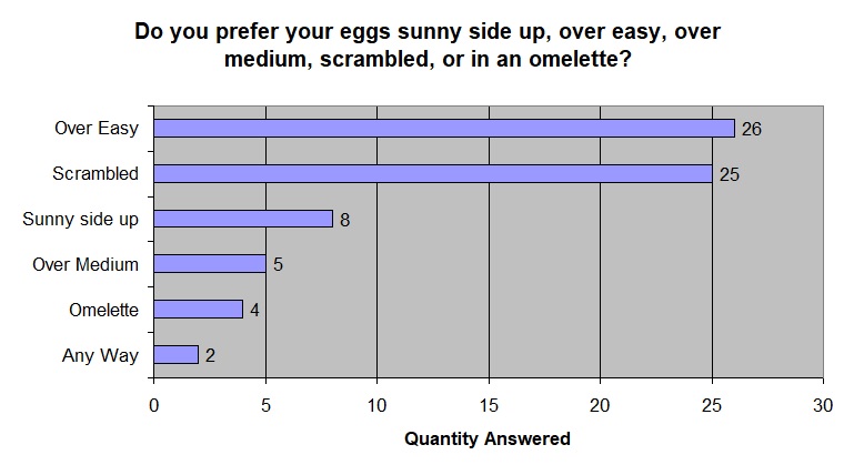 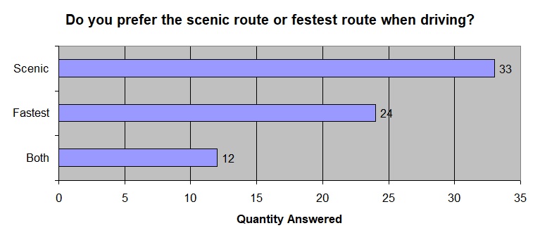 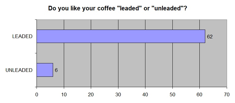 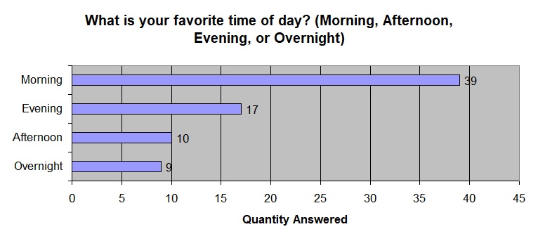 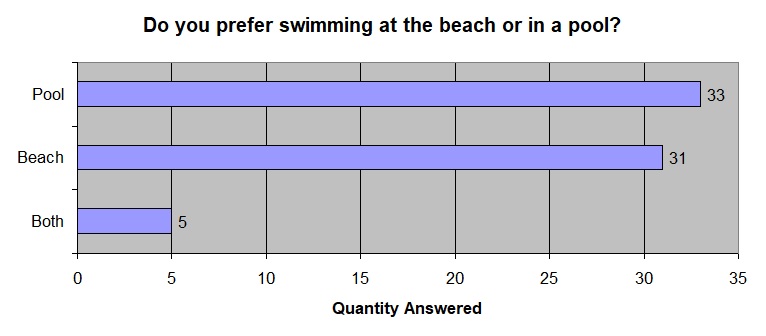  ECR BIRTHDAYS The following hams are celebrating a birthday over the next week. Happy Birthday to you all! NH7TR, Dick of Cibolo TX, has a birthday on Monday, August 1st KI5NMK, Randall of Spring TX, has a birthday on Wednesday, August 3rd KO4RXK, Derek of Clermont FL, has a birthday on Friday, August 5th Would you like your birthday recognized in the Newsletter and on the air during the Tech Net? Just send an email to Michael, K2SHF, with your callsign and birthdate. Your birthday will then be added to our spreadsheet.  THE ANTENNA FARM - By Charles KC6UFM Part 10 – The Fan Dipole Hello ECR Family, and welcome to The Antenna Farm. This is your friendly Antenna Farmer Charles, KC6UFM. 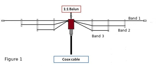 There are those who will argue that the Fan Dipole (see Figure 1) should be lumped in with the other dipole variants discussed in Article 7, but I disagree. The fan dipole is, at it’s core, a simple dipole, but it offers something that none of the other variants can provide: The ability to cover multiple bands without the need to switch anything and coverage all the way down to 160m if desired. True, the discone can do similar things, but the physical size of the discone limits it to the upper HF bands (even 15m gets iffy mechanically) and above. Also, the discone has about a 10:1 frequency range, and the fan dipole has no such limits. The fan dipole shown in Figure 1 is a simple, three band design. You will note that all three pairs of elements are connected to a common 1:1 balun at the center. No matter how many bands you want to cover, the elements all connect to a common center unit. As a rule, because the dipole (fan or otherwise) is a balanced antenna, you do want that center unit to be a balun. That said, again as a general rule, you don’t need to do any impedance transformation with a fan dipole. Like the simple dipole—albeit for different reasons—the fan dipole will typically show an impedance close to 50 ohms. Other than the center insulator/balun, fan dipoles can be made from just about anything that can conduct electricity. You can use individual wires for the elements. You can use TV style twin lead. I have used the ribbon cable found in computers and other electronics. You can even use plain old electrical extension “zip cord.” It all depends on how many bands you want to cover. You will need one conductor on each side of the center insulator for each band, so if you want to cover 40m, 30m, 20m, 15m, 10m, and 6m you should look for some sort of wire that gives you a total of six conductors...three runs of TV twin lead would work great. With that said, the closer together physically the individual wires are, the more they interact with each other. We’ll talk more about this later, but it is NOT a deal-breaker. Similarly, the more spread out the wires are, the less they interact. Lastly, the larger the diameter of the individual wires, the more bandwidth the fan dipole will cover. There is also some care needed when picking what bands to cover. Essentially, the closer two bands are to each other in terms of frequency, the more the elements for those bands will interact. Again, this is not a deal-breaker, but as you are tuning the fan dipole, remember that you may have created some additional work for yourself. I personally have built fan dipoles to cover every single ham band from 160m up through 1.25m, That’s 13 bands from 1.8 MHz to 225 MHz. Honestly, these kinds of fan dipoles can take me three days to tune, and that’s working 8-10 hours a day. By the same token, a fan dipole for 20m, 15m, 10m, and 6m can be tuned in less than an hour. So, how does this magic work? Easy...as Kurt Vonnegut said, “Science is magic that works.” Antennas As Filters We’re not going to go over all the information on dipoles here again. Go back and see Articles 6 and, to a lesser degree, 7. The individual element pairs of the fan dipole work exactly like a simple dipole. In Article 7 where we looked at the discone, we learned that the disadvantage of that very broad-banded antenna is that it can (and does when used with almost any HT, even the top of the line rigs) emit out-of-band signals. This is because antennas can—and do—act as the last filter in your transmitting chain. An antenna designed and tuned for band A will not be very good at radiating a signal on band B, assuming no harmonic relationship between the two bands. The discone, by design, will emit well on everything between bands A and Z. A simple dipole is tuned to radiate on one particular frequency, and it is VERY good at doing that. Apply a non-harmonic signal to that same dipole, and it will often have staggering losses and be a very poor radiator. The fan dipole takes advantage of this simple fact. Let’s say we build a fan dipole to work on 30m, 17m, 10m, and 6m. These four bands are not harmonically related. When we apply a 30m signal to the common feed point, the 30m elements have a low impedance (about 73 ohms) while the 17m, 10m, and 6m element pairs all present a much larger impedance (typically in the thousands of ohms). Electricity, even at RF, will take the path of least resistance. So the 30m pair gets the VAST majority of the energy. A similar thing happens when you apply other signals. Remember all that talk above about interaction? This is where and why it happens… 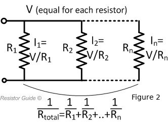 To explain how this works, let’s look at a simple DC circuit with simple resistors. See Figure 2. In a circuit where you have resistors in parallel, the voltage (E) is equal in all legs of the circuit containing the resistors. The current (I), however, is split between the resistors based on their individual resistance (R). This current can be found with Ohm’s Law by dividing the voltage by the resistance. We’ll assign an arbitrary value to E of 100 volts. If we assume that R1 is 73 ohms, then the current through R1 will be: 100 / 73 = 1.4 amps Now, if we assign a value to R2 of 5000 ohms, the current through R2 will be: 100 / 5000 = 0.02 amps As you can see, no matter what, there will be a current through R2, but it will be MUCH smaller than the current through R1. So most of the energy will be handled by R1 (140 watts) while R2 will only handle 2 watts. Now, make the shift from a DC circuit to RF. All you need to do is change “resistance” to “impedance” in your head. At some frequency, R1 will be about 73 ohms impedance while R2 will be some other, much higher value. So only R1 will put out an effective signal. But… As the resonant frequencies needed to get the pairs of elements to 73 ohms get closer together, the difference in impedance between the two nearby elements gets smaller and smaller, so they begin to have more of an impact on each other. There is one more thing to think about...again, look at Figure 2. Resistors (or impedances) in parallel combine according to the equation near the bottom of the figure, but we’re going to do some algebra to make it easier: Rtotal = 1 / (1/R1 + 1/R2 + … 1/Rn) This means that the total resistance (or impedance) will always be smaller than the value of the lowest resistor (or reactance). Using the values from our example above, we find that: Rtotal = 1 / (1/73 + 1/5000) = 1 / (0.0137 + 0.0002) = 1 / 0.0139 Rtotal = 71.94 Ohms This is why we can use a 1:1 balun and not get all wrapped up around the axle on matching to the fan dipole. Odds are, the resistive component of the impedance will be something less than 73 ohms due to the installation itself, but you have the additional impact of the several resistances in parallel pulling it down even more. Don’t feel bad if you have to go over this a few times to grasp it. It is, for some people, a new concept and may need some time to sink in. Calculating and Cutting Elements This process is exactly the same as for a simple dipole. Look back to Article 6 and find Equation 8. The equation is: L = 467 / F Where: L = Total Length of Dipole (½ wave) F = Frequency in Megahertz (MHz) All you need to do is calculate the total dipole length for each band of interest, cut a piece of wire that length, and then cut that in half to get the individual elements for each band. And trust me...use some masking or duct tape to keep the two elements together and mark EACH element with the band they are for. It’s easy to get all these wires mixed up! The equation will, as with a simple dipole, give you a length that is actually a little longer than what you need. This “extra” wire will be used to make the connections at the center insulator, adjust the elements to resonance on each band, and to attach insulators to the free ends of each element. As is, the elements will resonate at a lower frequency than you used in the calculation. For the calculation itself, select a frequency near the center of the band segment you are interested in. For example, if you are looking at 10m and want to work CW, SSB, and digital modes, a good place to aim for is around 28.3 MHz. How precise you need to be in your measurements and cuts depends largely on the band you’re working with. As you move higher in frequency, the tolerances get physically smaller. This means that at, say, 80M, you can be within a few inches, perhaps even as much as a foot, but when you are cutting an element for 1.25m, you need to be within a half inch or better. The Center Insulator As discussed above, the gizmo at the center of your fan dipole serves two main functions: 1) It provides mechanical support to the wires and the antenna overall. 2) It contains a 1:1 balun to match the balanced antenna to unbalanced coax. You can either buy or make a center insulator. Sometimes the making of a center insulator with a built in balun can require some special tools and skills, but in general, it’s not too bad. What makes this easier is that for a dipole, all that is needed is a “Current Balun” and all this comes down to is a few ferrite beads of an appropriate mix (usually either mix 31 or 43) large enough to slip over your coax and placed as close to the PL-259 as possible. It’s best to tape the beads in place when you have them installed. Just remember that if you make your center insulator/balun, it must be physically strong enough to support the weight of the entire antenna. 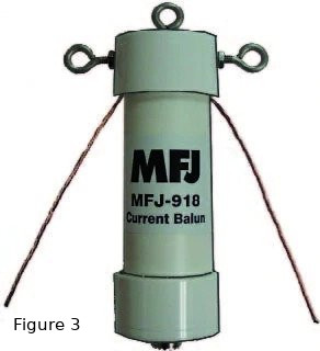 Figure 3 shows a commercially made center insulator with a 1:1 current balun from MFJ. This unit is priced at around $60 MSRP and can usually be had for closer to $40 at many ham radio shops. You can usually find similar units at ham fests for around $15 or so. You can buy the beads for around $15 on eBay. Notice the three eye-bolts...one at the top, and one on either side. Your elements connect to the eyes on the sides while you can use the top eye to hang the insulator—and so the entire antenna—from some support. All of the elements should be securely connected to the side eye bolts and then soldered to the balun’s feed wire to make good mechanical and electrical connections. Deployment Like simple dipoles, the fan dipole can be deployed as either a “Flat Top” (elements horizontal, parallel to the ground), as an “Inverted V” (with the elements sloped down from the center insulator toward the ground), or as a “Sloper” (with one end high and the other end sloping down toward the ground). Given the mechanical issues likely to come up, a vertical arrangement (with the element perpendicular to the ground) probably isn’t an option, but it would work well as an onmidirectional antenna if you want to deal with the mechanical problems. One deployment that does not work well with a fan dipole is as a “Straight (or Inverted) L” (sometimes called a “Tall L”) where one set of elements is horizontal and the other set vertical. While you can see this if you model the fan dipole in EZNEC, just know that the problem comes in with crazy interactions between element sets. No matter what deployment works best in your situation, remember to keep the ends of ALL elements positioned so no one can come into contact with the high voltages that will be present there. As mentioned earlier in this article, interactions between elements can be reduced if you are able to spread the free ends of the elements apart, or fan them out, from the center insulator. This does add a unique challenge to fan dipole deployment in that you are now working in all three dimensions rather than in just two. Tuning will be much easier if you are able to fan the elements out as much as possible. Tuning the Fan Dipole To quote Major Payne, “...we gonna start the hard stuff...” Tuning a fan dipole can be a challenge, but it is doable. You will need patience, judgment, perseverance, and time. Maybe lots of time. Oh, and an antenna analyzer or VNA. The fan dipole can be tuned using an SWR meter and a transmitter, but you can count on the time needed to double and the results to be marginal at best. You really need an analyzer or VNA. The tuning process comes down to adjusting each pair of elements to reach two goals: 1) Achieve resonance. 2) Minimize element interaction. Recall that when we cut the elements, they were all a little longer than they needed to be, and this is where that comes into play. Being slightly longer than needed for the band, the elements will resonate at a slightly lower frequency than you calculated. It is important that you have the antenna in it’s final operating position if at all possible to see how the elements will interact. As the antenna changes position, the interaction between the elements also changes. This is far and away easiest in an inverted V deployment since the ends of the elements are close to the ground...you might need a ladder to reach them. Connect your analyzer/VNA to the SO-239 port on your center insulator. It’s just fine to use a length of coax here...remember that unlike simple SWR meters, analyzers and VNAs are not fooled by the feed line. Next, adjust your analyzer/VNA for the design frequency of the LOWEST band of your fan dipole. The display should show you the complex impedance of the lowest frequency elements in the form of Z = R + (±jX). Do NOT pay any attention to the SWR reading...it is less than meaningless! Now, this is where you need the judgment part...remember that if the reactive portion of the impedance is negative, your dipole is too short and if inductive, it is too long. If you did the calculations and cutting correctly, it should be too long and show inductive reactance. Trim small, equal amounts of wire from the end of EACH of the element wire pair, and then recheck. It is far better to make a number of small adjustments. If you make a large adjustment, you risk cutting the wires too short, and then you’ll have to add equal lengths back to the elements. And remember that you will need enough wire to make a good, secure connection to the end insulator. Take your time (patience) and don’t give up (perseverance). Don’t worry about the resistive component of the impedance. It will end up taking care of itself. Once you finish with the element pair for the lowest frequency, move up to the next highest frequency and repeat the process. Keep doing this until you get to the highest band in your design. After you have adjusted the elements for all of the bands covered by your antenna, go back and check every band again from lowest to highest. If you were careful in the first pass, everything should be very close, but you can make additional adjustments if needed. Once you have all of the bands adjusted to a point where you are happy, you can now make the connections to the end insulators permanent by using good mechanical attachments and soldering. Again, as you increase the number of bands your fan dipole will cover, the tuning process becomes more complex and time consuming. Finally, we need to look at the bands you want to cover. Bands that are very close together (like 20m, 17m, 15m, 12m, and 10m) can give you fits as the interactions can be profound. Also, harmonically related bands (like 80m, 40m, 20m, and 15m) can also complicate things for the same reasons. But all of these can be done with some patience. And remember that the more you can fan out the wires, the less problems you will have with element interaction. I would suggest that, for your first fan dipole, you limit the number of bands to three or four and spread them out a little. A good choice for a beginner would be 15m, 10m, and 6m. All of these bands are available for at least CW to all hams regardless of license class and there are no harmonic relationships. Additionally, this antenna will be smaller and easier to handle. Another thing to consider is that because fan dipoles are so cheap to make, you can actually build “practice” antennas that you have no plans on using, then tear them apart and recover the components. Later, as you gain more experience with dipoles in general and fan dipoles in particular, you can go for the big guns. Lastly, remember that the fan dipole has all of the properties of a simple dipole...they are easy to build, can be made (using the right color and gauge of wire) almost invisible, and perform very well. The major lobes of the radiation pattern will be, like a simple dipole, broadside to the wire, so you may want to look at how the antenna is oriented when deployed. And remember, from many parts of the US, Europe is north-northeast. That’s all for this time around, my fellow farmers. Next time on The Antenna Farm, we’re going to look at mobile antennas. Take Care & 73 de KC6UFM Charles JUST AHEAD IN RADIOSPORT Taken from the ARRL Letter August 2 -- Worldwide Sideband Activity Contest (phone) August 2 -- ARS Spartan Sprint (CW) August 3 -- Phone Weekly Test (phone) August 3 -- 144 VHF-UHF FT8 Activity Contest (FT8) August 4-5 -- Walk for the Bacon QRP Contest (CW) August 4 -- SKCC Sprint Europe (CW) August 5 -- QRP Fox Hunt (CW) Visit the ARRL Contest Calendar for more events and information. HOW CAN YOU HELP OUT WITH THE NEWSLETTER? Looking for inspiring journalists to interview various ECR ham radio operators on a monthly basis for the ECR newsletter. The interview will concentrate on amateur radio related interests. The pay is on the extreme end of low. No paid vacation or medical benefits. If interested please contact Michael K2SHF, Ben K8BWK, Tom KE3GK or Scott W2BLT  YACHT NEWS for July 30, 2022 Young Amateurs Communications Ham Team, K8KDZ Sailing Through Radio Waves Connecting Young Hams, Creating Friendships, Expanding the Voice of Youth in Ham Radio Inspiring Youth with Enjoyment & Technology of Ham Radio -------------------------------------------------------------------------------------- Keep us in your sights through our echolink chats Mon. to Fri., YACHT youth net on Sat. and DYG/YACHT net on Sun. all at 7pm CDST on node 954283. Also follow us on Facebook and YACHT NEWS. We can also be found most Saturdays around 1:30pm on 20 meter HF above 14.310 depending on conditions ---------------------------------------------------------------------------------- NET REVIEW... Excellent turnout for the Saturday youth net. 31 stations showed up on my screen, but 6 left before they were called or did not respond. 16 youth hams climbed aboard: 2W0KYH, K0NNK, KD9KYU, VA3BHT, KE8IKS, N6RWC, KE0ZNV, KD2WTR, KL5IS, KD9VGV, KI5VLG, KE8LQR, KC3RAP, KN4VKW, KN4VKY, KQ4AKR. Thanks to our "bright stars" and to al others who boarded our cruise on the waters of YACHT ham radio. CHAT SESSIONS... Monday: 8 hams went for this evening's cruise, 6 youth included: KL5IS, VA3BHT , KE8LQR, KF0JFQ, KE8RJU, KQ4AKR, also K7JKA and KC0HFQ Tuesday: 13 stations, VA3BHT, KE8LQR, KI5JXQ, KE8TJU, KC3RAP, KE8TYU relay from Katie, and 7 others. Come along with us this evening as we link in to the E.C.R. and enjoy another evening ham cruise. MEMBER QRZ PAGES... Newly updated is the page of Finn https://www.qrz.com/db/KD2WTR Lots of stuff to see here. And here is the brand new updated site for Ryan http://www.qrz.com/db/n6rwc Ryan also mentions this... " "I would also like to point out that I am offering free QSL management, cards only, for any youth ham." YACHT MEMBER AT COUNTY FAIR... Video of Jaden Smith KE0NVA interview [link] NEW MEMBERS WELCOME... Our 2nd newest youth member is Adam VA3BHT from Toronto, Canada. He is 13, a newly licensed ham and a Sea Scout. Nice to have a member from our neighbor to the north. And our newest youth member from West Malaysia Lada 9W2LXW. http://www.qrz.com/db/9w2lxw He is 14 and requested membership. He joins Karl 9W2IXY as our 2nd member from Malaysia and is looking forward to meeting many of you on Echolink. It is amazing to see YACHT recognition spread worldwide. Lada is the 50th new youth member added this year. Our current membership numbers added in 2022 are 50 youth and 14 adults, total of 54 new member additions. If you are reading this and have yet to connect up or have only done so a few times, consider doing so soon. We want to hear from you. We appreciate those who check in on a regular basis or often. Your support is essential to our high level of activity. DX-PEDITION OF THE YEAR... Starts Mon. July 25 to July 31 [link] This is one not to miss if you have the capability. It is a rare one for sure. YACHT MEMBER WINS AWARD... Ryan KN4VKW received several awards at a baseball tournament in Lexington, KY, Best pitcher with ERA of 1.00 among them. Blake on left and Dad on right  COLT CLARK & KIDS... This delightful family band is back with a popular Beach Boys tune https://youtu.be/719cvPx_C4s -- 73, Ed Engleman KG8CX http://yacht.younghams.org/ http://yachthams.webstarts.com/index.html http://w8pif.webstarts.com/index.html http://www.qrz.com/db/k8kdz ARRL FIELD DAY 2022 CONTACTS RISE TO OVER 1.2 MILLION Taken from The ARRL Letter dated July 28, 2022 Updated numbers from ARRL Field Day 2022 now show 1,235,265 total reported contacts as of July 26, 2022. ARRL Contest Program Manager Paul Bourque, N1SFE, reported that 4,774 Field Day entries have been submitted, and there were 28,250 Field Day participants. The class breakdown is as follows: 1,141 Class A (club / non-club portable) 598 Class B (one or two person portable) and Battery (one or two person portable) 56 Class C (mobile) 2,093 Class D (home stations) 735 Class E (home stations using emergency power) 151 Class F (Emergency Operations Centers) The last day to submit entries was Tuesday, July 26, so the numbers will change in the coming weeks. Bourque added that 237 entries are missing, either the required dupe sheet (or in lieu of that, a Cabrillo-formatted log) or supporting documentation for claimed bonus points. He encourages all entrants to check the ARRL Field Day Entries Received page at http://field-day.arrl.org/fdentriesrcvd.php to verify that their entry has been accepted, and if it is complete or pending any supporting documentation. Additional documentation and log files can be added to previously submitted Field Day entries by using the link that was provided in the confirmation email that was received upon submittal. Any questions regarding Field Day entries should be directed to fieldday@arrl.org. |
| FACILITATORS Dick WB2JPQ Henry WB4IVB Emil WA2UPK Bob KB3SNM Tony W2KJV Kevin VE3BZ Paul W4END David KB4FXC Kevin KE7K Joe KO4FRR Mike K2CMT Michael K2SHF Steve K2EJ Keynon KB5GLC Dan KD2VNU Caleb KO4UYJ |
ECR ACCESS IRLP 9050 AllStar 27339, 45192, 45225 Echolink WB2JPQ-R(57780), WB2JPQ-L(375103) DMR Brandmeister 3129973 DMR TGIF 9050 System Fusion 44444, 92805 DStar XRF(XLX)256E HamShack Hotline 94049 P25 31582, 9050 M17 M17-ECR Module A Hams Over IP 15001 NETS Tech Net Tuesdays 8PM ET Morning Brew Mon-Fri 7AM ET YACHT Youth Net Wednesdays 8PM ET |
WEBPAGE http://eastcoastreflector.com ZOOM ROOM Open 24/7. All are welcome! ID: 83929643320 Password: 193414 http://bit.ly/ecrdaily MERCH SHOP http://bit.ly/ecrshop TECH NET LOG http://bit.ly/ecrtechnet YOUTUBE CHANNEL http://bit.ly/ecrYouTube |