
| Newsletter
Home | ECR
Homepage | ECR Shop
| ECR
YouTube | ECR
Groups.io | ECR
Facebook |
September 5, 2022
 MORNING BREW Q&A - By Michael K2SHF Thank you to all who checked in to the Morning Brew. The following are answers to some of our recent daily questions. We asked the following questions. As always, only answers with a tally of 2 or more were included below. Thanks to Derby Dan (KD2VNU) for his hard work in logging the answers and tallying the results after each net. 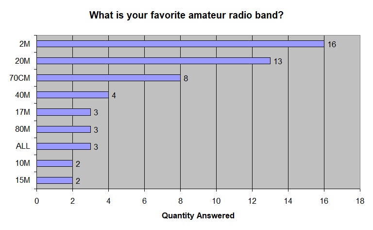  ECR BIRTHDAYS The following hams are celebrating a birthday over the next week. Happy Birthday to you all! K8BAC, Al of Britton MI, has a birthday on Friday, September 9th Would you like your birthday recognized in the Newsletter and on the air during the Tech Net? Just send an email to Michael, K2SHF, with your callsign and birthdate. Your birthday will then be added to our spreadsheet.  THE ANTENNA FARM - By Charles KC6UFM Part 12 – Common VHF/UHF Mobile Antennas Hello ECR Family, and welcome to The Antenna Farm. This is your friendly Antenna Farmer Charles, KC6UFM. Today we’re going to build on the general information found in Article 11 , Introduction to Mobile Antennas, and take a closer look at a few of the common antenna designs used for VHF and UHF operations. We will also take a fast look at using some of these mobile antennas in a fixed (or base) station setting. In this article, I will assume you have read and understand the concepts presented in Article 11, particularly the areas of ground bonding and power supply wiring. So, grab your shovel and let’s head out to the Farm! All of the antennas we’ll look at today are variations on the simple dipole. More specifically, these are all essentially similar to the quarter-wave ground plane, except we use the vehicle body (ground) provides the needed ground plane. The Quarter-Wave Vertical  The first, and simplest, of the mobile antennas is the Quarter-Wave Vertical. As the name implies, the radiating element is an electrical ¼ wave long. This is, as you will recall, identical to the ¼ wave ground plane discussed briefly in Article 3 (see Figure 1). The only difference is that instead of a set of radials providing the ground plane, the body of the vehicle will do this task for us. The theoretical current distribution on this antenna will be identical to the ½ wave dipole (mounted vertically), but environmental factors will almost certainly distort that current flow and, therefore, the radiation pattern. This is mostly because the ground plane is made up of a non-tuned system, that is, the car body is not a “perfect” quarter wave. In other words, this antenna is NOT balanced because the two halves are not electrically identical. The good news is that we can feed the quarter-wave vertical directly with coax. As you recall, the impedance of a simple dipole in free space is around 73 ohms, but a typical installation will lower this to close to 50 ohms due to elevation, ground losses, surrounding items, and other factors. The same applies to our quarter-wave vertical, but the single biggest factor is the less-than ideal ground. Most commercially made quarter-wave verticals have a ferrule with a set screw to make small adjustments to the effective length of the radiator. Typically, you can slide the whip in and out of the ferrule about an inch, maybe a little more. Most of the manufacturers also provide a whip that is longer than needed for the lowest frequency of the antenna’s range. The idea is that you can trim small amounts from the whip until you get close to the desired resonant point, and then make fine adjustments by sliding the whip up or down to get dead on spot. Just be VERY careful to avoid trimming the whip too short. If you do, you’ll be buying a new whip.  One of the downsides to the quarter-wave vertical is it has a fairly high take off angle. See Figure 2. As you can see the point of maximum gain is at 22 degrees above the horizon. For many operations, this is a bit higher than optimal. Also, in most applications, this number will likely be lower due to the issues of the flaky ground system, usually on the order of around 18 degrees. And, in a handful of cases, this high take off angle may be a good thing… Here in San Diego, most of the repeaters are on mountain tops around the main part of the metro area. In most situations, you are driving around town at an elevation of usually less than 500 feet. The repeaters are almost all at 3000 feet or higher. All of a sudden, that 22 degree (or so) take off angle looks much better. Most of your signal is being aimed at the repeater’s elevation instead of at the base of the mountain where the repeater lives. And this situation is far more common than most think. If you are, for example, in Denver, you’re close to a mile in elevation, but the repeater you’re working could easily be a mile and half or more. The biggest disadvantage to the quarter-wave vertical is that it is just a simple dipole turned on its side, and so has 0 dBd gain. It’s a unity gain antenna. Since we’re talking about VHF and above, the size of the antenna isn’t a big factor (except at 6m and, perhaps, 2m), and we can do much better. The Half-Wave Vertical  The Half-Wave vertical antenna is simply the vertical, mobile version of the EFHW we looked at in Article 7 (see Figure 3). Similar to the quarter-wave vertical, the half-wave vertical uses the vehicle body as it’s ground system. Otherwise, the mechanical design of the half-wave vertical is very similar to the quarter-wave usually using a sliding whip portion to fine tune the resonant frequency. 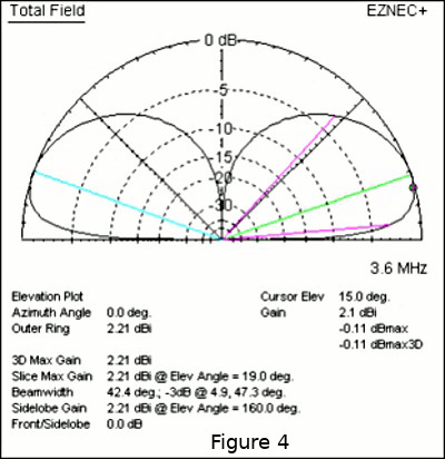 The big advantage of the half-wave vertical is that it has a lower take off angle. See Figure 4. As you can see, while the quarter-wave vertical has an angle of radiation around 22 degrees, the half-wave variant is around 15 degrees. Again, the actual on-the-air angle of radiation will be a little lower still, probably around 12 degrees or so. I want make sure you understand that there are times when a low angle of radiation can be a disadvantage, but in the vast majority of cases, lower is better. You will need to assess your particular situation to make sure what you need, but when in doubt, go lower. Remember that the quarter-wave antenna is a unity gain system. Now think back to what we have learned about gain overall...any antenna, regardless of it’s gain, will radiate the EXACT same total energy as an isotropic antenna. Antenna’s exhibit gain because they are radiating more energy in some directions than in others. It just so happens that the quarter-wave antenna is a modified simple dipole, and therefore has the same gain (2.14 dBi) as the dipole. The half-wave, however, pulls the radiated signal closer to the horizon, thereby “stealing” some energy from higher take off angles and pointing it lower. Therefore, the half-wave vertical does show some gain over a quarter-wave, typically on the order of 2.21 dBi, or 0.07 dBd. This should dispel some of the myths you may have heard about half-wave verticals. There is one popular myth that makes the rounds on YouTube and the assorted mailing lists that, somehow, the half-wave vertical will double your signal strength. It doesn’t. The biggest issue with a half-wave vertical is that, just like the EFHW, the feed point impedance will be much higher than the typical coax feed line, usually close to 3000 ohms. You can, like with the EFHW, use a transformer type matching system, but this will tend to introduce even more loss into an already high loss system. A better solution for mobile applications as far as loss is concerned is, in my opinion, a transmission line match. If we assume that we are building a half-wave vertical for 2m, we could use our analyzer/VNA to determine the feed point impedance at 146 MHz, and then calculate the needed quarter-wave impedance matching feed line. Using the calculator at https://www.everythingrf.com/rf-calculators/quarter-wave-transformer-impedance-calculator and a feed point impedance of 2800 ohms (fairly typical), we would need a quarter-wave (just more than half a meter, but measure it with your analyzer/VNA) of 375 ohm feed line. While transformers are high loss devices, they are much easier mechanically than the more efficient feed line match, especially in a mobile setting. While there are few half-wave verticals on the commercial market, the few out there all use transformers. The Five-Eighth’s Wave Vertical 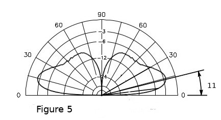 The 5/8-Wave Vertical is, far and away, the most popular antenna in mobile VHF/UHF use. It is, as the name implies, 5/8 of a wavelength long. See Figure 5. Much of the information on the half-wave vertical also applies here, but the big difference is that once again, the angle of radiation has dropped and the gain has increased. You will note, however, that the 5/8-wave has a pair of new minor lobes pointing up at around 70 degrees, so the gain of the 5/8 over the ½ is not as much as you might expect. The big advantage to the 5/8 is that low take off angle. Again, most installations will have an even lower take off, typically in the range of 6-8 degrees. And, again, this may or may not be an advantage in all situations, but generally, it will be of some benefit. Also, as with the 1/2-wave, the 5/8-wave will have a relatively high feed point impedance, though not as high as the 1/2-wave. Typical values will fall between around 100 and 400 ohms. Other Mobile Antennas According to the several mobile antenna manufacturers, the above three variations make up almost 98% of all installations. That isn’t to say that these are all the possible antennas. There are 3/8-wave, 3/4-wave, full wave, and other lengths. There are also mobile antennas that can do omni-directional horizontal polarization. There are many others that meet specific needs, but here on the Farm, we’re just looking at the big three for now. Impedance Matching Mobile Antennas This section pertains only to the 1/2 and 5/8-wave verticals. The 1/4-wave needs no special care for the impedance as it will be close enough to 50 ohms. Despite my own fascination with feed line impedance matching, for pure mechanical (and electrical) simplicity, mobile antennas are best served with some form of transformer impedance matching systems. In almost all commercial antennas, this is done with a “Linear Coil” transformer. This is mostly a cost versus performance decision made by the manufacturers. A toroidal transformer would be cleaner (in terms of RFI) and more efficient, but it would be much more expensive. At the power levels used by most hams for VHF/UHF mobile operations, the lower RFI and increased efficiency of a toroidal core transformer just isn’t worth the extra costs.  A linear coil transformer is just what it sounds like...a coil of wire in a straight line. See Figure 6. They all look pretty much alike and are often, mistakenly, referred to as “Base Loaded” antennas. In the VHF and UHF ranges, base loading is a waste of time, energy, and money. These are all the same because the matching network is, essentially, the same. 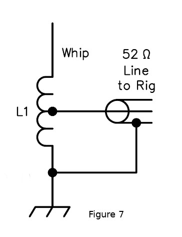 Inside that plastic cup at the base of the antenna is the matching transformer. Technically, it is an “Auto-Transformer” matching system. An auto-transformer is just a pair of coils with one end of coil A connected to one end of coil B. This is shown schematically in Figure 7. As you can see in Figure 7, the entire coil is connected between the whip and ground (body). The shield of the coax goes to ground as well. The center conductor of the coax is attached to the coil “someplace” between the whip and ground. This is important because while we could calculate the exact point of connection for the coax center, it would be based on a perfect ground, and your car is NOT a perfect ground. You have to experiment by moving the tap up and down the coil until you find the best match. Again, an analyzer or VNA will make this MUCH easier and faster, but it could be done with an SWR meter. This means you are tuning the match over the actual ground it will be operating with. “But, wait...” you say. “I can’t adjust the coil tap on my new Super-Whiz Bang antenna!” No, you can’t. At least not without breaking into the little plastic cup. The fine folks at Super-Whiz Bang have made a guess for you, and chosen a sort of generic tap point. Sometimes they do a good job. Other times, as they said in Indiana Jones and the Last Crusade, they choose poorly. Odds are, it will at least work. Maybe not well, but it will work. If, on the other hand, you are building your antenna, you can have it dead on. I don’t mean to imply that the coil matching system can replace having a good ground. Not at all! You still need the best ground you can make. Summary Of Antenna Types Which of the three vertical antennas we have looked at is right for you? I can’t answer that. As you move from ¼ to ½ to 5/8-wave antennas, the angle of radiation gets lower and the gain increases. The gain increases are very small. The take off angle will have a much larger impact on your signal than the actual gain. In the vast majority of cases, lower angles are better, and that stacks the deck in favor of the 5/8-wave. However, there may very well be other issues in your normal, day to day operations that could make the 1/4-wave a better choice. You have to make that choice. 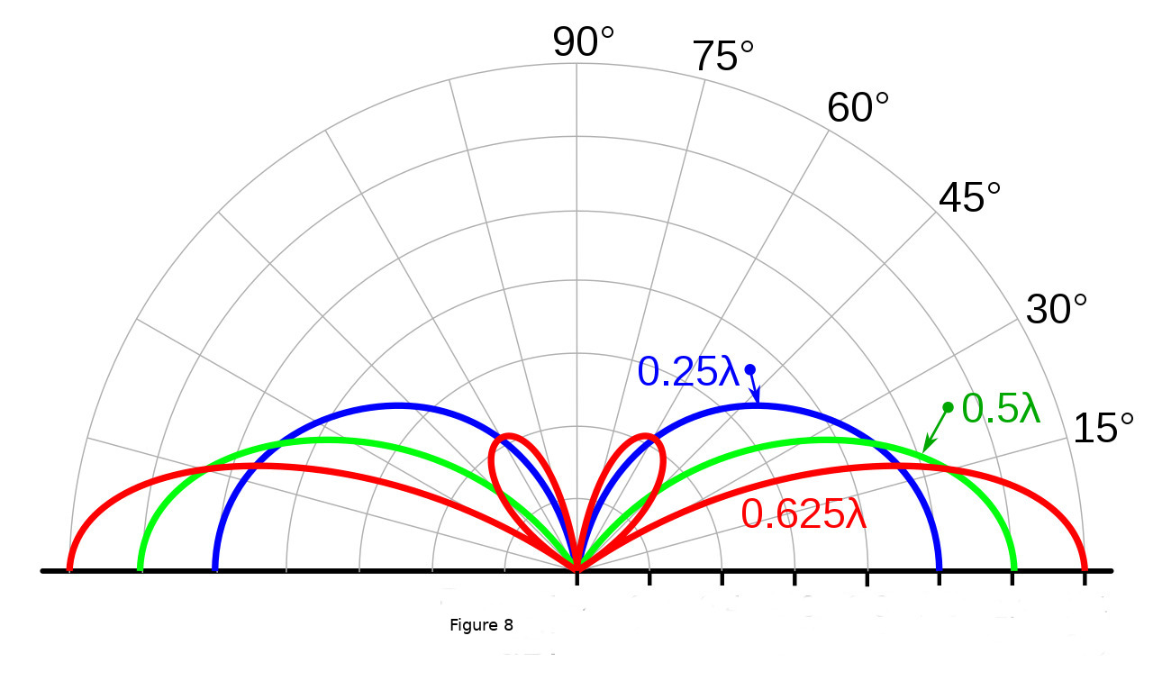 Figure 8 summarizes visually the relationships between the 1/4-wave, 1/2-wave, and 5/8-wave antennas in terms of take off angle and gain. Dual (and more) band radios are very popular and reasonably priced. The same applies to multi-band mobile antennas. The design of a multi-band antenna is a bit complicated and quite tedious in the math department. This is because you have to find points where harmonics, lengths, element diameters, matching coils, and traps all align. In a later article on antennas mostly for HF multi-band use we’ll get into that process. For now, let’s just say that you will need to combine sections of the overall antenna in ways that will (hopefully) increase gain at the higher bands while maintaining at least unity gain at the lowest band. Sometimes, even for commercial antennas, this doesn’t end well. When it does, there can be some strange bedfellows…like a 1/2-wave feeding a 3/8-wave through a delay line. Yeah...it can get weird. To make it even crazier, most manufacturers lie about what they have done. Using Mobile Antennas At A Stationary Location This is entirely possible. We can do this fairly easily.  Just because we CAN do it, that does not mean that we SHOULD do it. See Figure 9. You can’t, as you should know by now, just zip-tie a mobile antenna to a 2x4 in the back yard. You MUST have a ground! The easiest way to do this is with a mag-mount antenna. Get yourself the biggest pizza pan or cookie sheet you can find, nail it to the roof of your house with a block under one side to make it level, and stick the mag-mount antenna to that. Remember that the pan MUST be at least 1/4-wave all the way around the antenna, that is, 1/2-wave length in diameter. If you’re trying this for 2m, the pan must be 1m in diameter, nearly 4 feet! At 70cm, it only needs to be 35cm (about 18 inches) in diameter. There are also so-called “Adapters” from various manufacturers that allow you to add radial-like appendages to the base of a mobile antenna. They are a bit on the pricey side and don’t work as well as a big pizza pan. They might, however, be your only option for a 2m set up. I’ve never looked for one, but I would think 4-foot pizza pans are both hard to find and expensive. But the best way to use a mobile antenna for a base station is to forget the idea and build a base antenna. Odds are, by the time you buy the antenna and a big pan, you’re going to spend more than you would a good base antenna. Plus, you’re going to get much better performance and a better signal, both of which are high on the list of Good Amateur Practice. This will make you a better operator. That’s all for this time on the Farm. Next time we’re going to have a look at portable antennas, including HT antennas. Take Care & 73 de KC6UFM Charles TECHNICIAN CLASS LICENSING COURSE TO BEGIN IN SEPTEMBER - By Steve K2EJ FREE & Weekly w/ Zoom Amateur Radio Technician Class Licensing Course Begins Thu. Sept. 8th thru Thu. Oct. 20th in 7 sessions Each 3-hr session start @ 6:30 PM ET Sponsored by National Electronics Museum Email roland dot anders at comcast dot net HOW CAN YOU HELP OUT WITH THE NEWSLETTER? If you have any interest in giving us a hand, please send an email to K2SHF. Send us links, articles, pictures, anything really. And if you have knowledge in a subject that you think our readers would find interesting, perhaps you could write some articles. "This is a team effort".  YACHT NEWS for September 3, 2022 Young Amateurs Communications Ham Team, K8KDZ Sailing Through Radio Waves Connecting Young Hams, Creating Friendships, Expanding the Voice of Youth in Ham Radio Inspiring Youth with Enjoyment & Technology of Ham Radio Making a Difference Through Ham Radio -------------------------------------------------------------------------------------- Follow us on Facebook, YACHT chat session and youth net, YACHT News ---------------------------------------------------------------------------------- NET REVIEW... Another well attended youth net. Youth operators heard from: 2W0KYH Declan, KN4VKY Blake, KN4VKW Ryan, N8JJM Joshua, K0NNK Collin, KN6ULC Quinn, KC1PEH Bradley, KE0ZNV Lyle, KE8NQQ Daniel, K8FI Joshua, K8JDT Jonathan (new member), KL5IS Asa, KI5QCK Jonathan (no audio). Thanks to all stations of all ages that connected up. CHAT SESSIONS... Monday: 7 youth check ins: KE8NQQ (now NC8R), KC1PEH, KF0JFQ, KC3RAP, VA3BHT, K0NNK, KE8LQR. 11 total. Tuesday: 14 connections and the following young hams: KE0ZNV, NC8R (new call), KF0JFQ, K8JDT, KC3RAP, KC1PEH, 9W2LXW, KE8LQR (in/out), AI7HE, VA3BHT. Thanks to all and others. YL SYSTEM YOUTH NET... Try and support the young ham net on Sunday morning 1500utc 10am CDST. Lyle KE0ZNV, Nick KO4PPD, Finn KDWTR are the YACHT members so far accepted as youth net controls. They can use more, both check ins and controls. Support their youth initiative as it is a new venture for this long established HF group. AB3TY, Larry is their president and a frequent check in to our YACHT chats and youth net. Due to church services, Sunday morning may not work for everyone, but if you can, support this net. Following post from Mark Strachan KD6IQW, Lyle's dad ... Mark Strachan Well first time publicized.. they had their first practice run last Sunday. For those interested in being an NC or relay, the YL system provides training! We want any and all youth to participate. No experience is necessary or required. Just have to have a General class license or above. QSO TODAY VIRTUAL HAMFEST... https://www.qsotodayhamexpo.com/ Eric Guth, the originator of QSO Today says this on the YACHT F.B. page Eric Guth Please come - it is one of the best ways to learn about all aspects of ham radio, in one place, and speak to the people who make it happen. Go here to view ALL presentations since 2020, really an amazing collection of informative topics including youth https://vimeo.com/showcase/qsotodayhamexpomar2021?page=4 Presentations of interest to YACHT: Katie & Liam 11am CDST on Sat. 9/17 -- Sterling Mann 2pm CDST -- Check sked for others. MEMBER FOCUS... updated QRZ pages for http://www.qrz.com/db/kn4vkw and http://www.qrz.com/db/kn4vky BIRTHDAY GREETINGS TO... Adam VA3BHT. He turned 14 on Monday. NEW CALLSIGN... Daniel, ex KE8NQQ is now NC8R a very nice call. Good choice. NEW SCHOOL RADIO CLUB... Ryan, N6RWC has organized and set up a radio club at his high school. More youth poised to experience the wonderful world of ham radio http://www.qrz.com/db/kn6voy NEW MEMBER ON BOARD... Welcome to Jonathan K8JDT from Gwinn, MI. He is 18 and brother to Daniel NC8R and Joshua K8FI. That's another U.P. youth ham on the YACHT team. YOU TUBE OF NEIL KD2ZDY... He is one of our newer adult members and requested we make his videos available, they are not radio related... https://www.youtube.com/channel/UCOgq4OznxV8zLNHtx_Z5i9g RC CONSTRUCTION TRUCKS... Not ham related, but men playing with realistic trucks. Fascinating https://www.facebook.com/watch?v=638192984279985 MORE GOOD MUSIC WITH COLT CLARK AND KIDS... https://www.youtube.com/watch?v=JECqPSwE0ek https://www.youtube.com/watch?v=x6VAUYCn2_w FOUND THIS POST ON FACEBOOK, GOOD ONE TO FOLLOW... ..."If you see someone falling behind, walk beside them. If someone is being ignored, find a way to include them. If someone has been knocked down, lift them up. Always remind people of their worth. Be who you needed when you were going through hard times. Just one small act of kindness could mean the world to someone. 73, Ed Engleman KG8CX http://yacht.younghams.org/ http://yachthams.webstarts.com/index.html http://w8pif.webstarts.com/index.html http://www.qrz.com/db/k8kdz ZOOM ROOM PRESENTATION - By Dick WB2JPQ Come join us in our Zoom Room on Thursday, September 6th, at 8PM ET for an RFI presentation by Jeff Stuparits W4DD. See Jeff's lastest article in the August edition of QST. Everyone is welcome. Access our Zoom Room by clicking this link. => http://bit/ecrdaily |
| FACILITATORS Dick WB2JPQ Henry WB4IVB Emil WA2UPK Bob KB3SNM Tony W2KJV Kevin VE3BZ Paul W4END David KB4FXC Kevin KE7K Joe KO4FRR Mike K2CMT Michael K2SHF Steve K2EJ Keynon KB5GLC Dan KD2VNU Caleb KO4UYJ Scott W2BLT |
ECR ACCESS IRLP 9050 AllStar 27339, 45192, 45225 Echolink WB2JPQ-R(57780), WB2JPQ-L(375103) DMR Brandmeister 3129973 DMR TGIF 9050 System Fusion 44444, 92805 DStar XRF(XLX)256E HamShack Hotline 94049 P25 31582, 9050 M17 M17-ECR Module A Hams Over IP 15001 NETS Tech Net Tuesdays 8PM ET Morning Brew Mon-Fri 7AM ET YACHT Youth Net Wednesdays 8PM ET |
WEBPAGE http://eastcoastreflector.com ZOOM ROOM Open 24/7. All are welcome! ID: 83929643320 Password: 193414 http://bit.ly/ecrdaily MERCH SHOP http://bit.ly/ecrshop TECH NET LOG http://bit.ly/ecrtechnet YOUTUBE CHANNEL http://bit.ly/ecrYouTube |