
| Newsletter
Home | ECR
Homepage | ECR
Shop
| ECR
YouTube | ECR
Groups.io | ECR
Facebook |
October 24, 2022
 ECR BIRTHDAYS ECR BIRTHDAYSThe following hams are celebrating a birthday over the next two weeks. Happy Birthday to you all! N2JWP, Mario of Deer Park NY, has a birthday on October 26th KD2YFO, Aiden of Whitney Point NY, has a birthday on October 26th W2HR, Harold of Grants Pass OR, has a birthday on October 28th KN4LEH, Dan of Haines City FL, has a birthday on October 28th W7RY, Jim of Ozark MO, has a birthday on October 31st WB8ODF, Dave of Ypsilanti MI, has a birthday on November 1st NA2F, Antonio of Champlain NY, has a birthday on November 1st KD2YHZ, Lucca of Whitney Point NY, has a birthday on November 6th Would you like your birthday recognized in the Newsletter and on the air during the Tech Net? Just send an email to Michael, K2SHF, with your callsign and birthdate. Your birthday will then be added to our spreadsheet. ECR STARTS NEW 40 METER NET - By Michael K2SHF The ECR has several nets happening right on the Reflector itself. But how about having one somewhere else, like on HF perhaps? That is what the ECR Think Tank has been discussing. Tom KE3GK, a member of "da tank", is very excited to be the net controller of this net which starts on Monday, October 24th. "I think it's a wonderful thing. It gets people off of VHF/UHF and onto HF, especially newer hams." said Tom in a recent interview. "It broadens their horizons, and also inspires technicians to upgrade to have access to this whole other world called HF." When Tom begins the net, he will come up with a topic each week for discussion. This week's discussion will be "The trials and tribulations of fall cleanup". Tom said he is always looking for topic ideas from everyone. Said Tom, "People can either email me or meet me in the [ECR] Zoom Room to give me new ideas for topics." Tom is also open to having other people act as net control so that they can get some practice being a net control operator. Tom further commented, "Since we will be doing Zoom simuntaneously, if a relay station hears somebody that the net control doesn't hear, we will be able to get their check in immediately so that we do not leave anybody out." If you have 40 meter capabilities, please join us on Monday evenings at 8PM Eastern Time. The net will be on or around 7245 KHz LSB. We are hoping for great conditions, lots of participation, and plenty of fun.  THE ANTENNA FARM - By Charles KC6UFM Part 15 – Intro to Yagis Hello ECR Family, and welcome to The Antenna Farm. This is your friendly Antenna Farmer Charles, KC6UFM. In the next few articles, we’re going take a rather in depth look at the Yagi antenna. Essentially, in this first article, we’ll look at the history, theory of operation, and behaviors of the Yagi, as well building a model of a simple dipole to see how the basic foundation of the Yagi works. The next couple of articles will deal with the design and modeling of Yagi antennas in more depth and how the design parameters of the several elements impact performance. The last article will deal with how to construct a Yagi. In all cases we will assume a 2m design and limit the number of elements to 4 to make things manageable and easily understood. These arbitrary limits in no way should be taken as the only thing a Yagi can do. As you will soon see, a Yagi is nothing if not flexible! I tend to use the 2m band when designing, modeling, and building test antennas. The 2m band gives you antenna that is small enough to be easily handled and large enough that the measurements need not be taken with a micrometer. That is, however, just my habit. You can use any band you like. Throughout these articles on Yagi antennas, I will be using the metric system for measurements. Since we talk about bands based on their wavelength in metric units, it makes more sense to use metric here. Just as an example, 148 MHz (the top of the 2m band) has a metric wavelength of 2025.6 mm, or 2.0256 meters. In a practical sense, it’s also easier to measure 1 mm than 0.04 inches. Also, throughout the articles, we will be using antenna modeling software. For ease of use, ability to be agile in terms of the design, and maximum operating system stability, I will be using EZNEC. To keep things at the lowest common denominator, I will use EZNEC 5, but more recent versions are almost identical in use. EZNEC is now free software and is available at www.eznec.com for the latest version. The free version of EZNEC 5 is available from several sources online. Note that EZNEC is a Windows program. Version 5 runs well in a Virtual Box with Windows 2000 or higher under Linux. The newer versions prefer real Windows 7 or higher. I would strongly suggest you get EZNEC so you can follow along as we design and model a Yagi antenna. I honestly have no idea of how to use EZNEC on an Apple Mac. If, however, you don’t want to use EZNEC, other software packages will be similar. With all of that out of the way, let’s get started… The Yagi antenna—more correctly the Yagi-Uda antenna—is one of the most recognized antennas used by Ham operators and was developed in 1926 by Shintaro Uda and Hidetsugu Yagi of Japan. It is an end-fire, directional array typically made up of one driven element and one or more “parasitic” elements set up as either reflectors (behind the driven element) or directors (in front of the driven element). The driven element (usually shown as DE) is a simple ½ wave resonant center fed dipole. The reflector (usually shown as REF) is slightly longer than the DE by about 3%-6%. Conversely, the directors (usually given as DIR) are slightly shorter than the DE, again by around 3%-6%. The distance between the several elements will vary from around 0.1 to 0.5 wavelength depending on the desired performance. 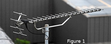 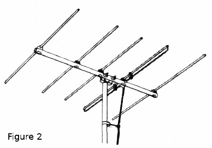 See Figures 1 and 2 for a pair of typical Yagi antennas. The antenna in Figure 1 uses a “Corner Reflector” instead of a simple dipole element. This gives a slightly better front-to-back ratio but it also narrows the bandwidth and is more complicated to build mechanically. Yagi antennas can be built for any frequency, but as usual, as the frequency gets lower, the antenna gets larger. In the case of the Yagi, the antenna gets exponentially larger! With a Yagi, you are dealing with a 2-dimensional antenna that has both length (the boom) and width (the elements), and both can get out of hand very quickly. Large Yagis can also get quite heavy and be hard to turn. Lastly, a Yagi puts a lot of metal in the air, so wind loading and ice build up can be a serious issue in some areas. In practice, the vast majority of Hams will never deal with—or maybe even see—a Yagi for the bands below 40m. Maybe even 20m. Yagis also lend themselves to multi-band designs. Yagis for 10m, 15m, and 20m are very common. A 5-band design can also be had. This is because with proper construction, element spacing choices, and a few other factors, the elements for all bands can coexist on the same boom with very little interaction. But where the Yagi really comes into its own is the VHF and higher bands. There are 6m, 2m, 1.25m, and 70cm quad-band Yagis all over the place. Even at 6m, a 5 element Yagi can be turned by a TV antenna rotor with no problems. Well, other than the lack of an efficient brake to stop the antenna from being moved by the wind. That 5 element 6m Yagi beam will also give you on the order of 9.5 dBd of forward gain. But forward gain is usually a secondary concern. Yes, that’s right...getting more forward gain is often not a good idea or the right thing to do. I’ll remind you that no antenna—not even the Yagi—can create power. Antennas show gain in a particular direction by “stealing” energy from other directions and focusing it in the desired direction. For a vertical antenna (base or mobile) this done by focusing energy at the horizon instead off into space. As a true directional antenna (that is, it focuses most energy in one direction at the expense of other directions), the Yagi creates one “Major Lobe” in the desired direction. This implies that the Yagi will show “Nulls” where the signal is lower than in the Major Lobe. Ofttimes, on receive, there will be some form of interference (either QRN or QRM) in some direction from your QTH. This interference can completely cover up the desired signal so you can’t communicate. With a Yagi, you can turn the antenna so that the noise is in a Null and so is radically reduced in apparent strength. This ability to block interference is usually of more importance to good amateur practice and operation than forward gain. There are two sets of Nulls on a Yagi that we need to look at: 1) The Null to the rear of the antenna, that is, opposite of (180 degrees) the Major Lobe. The ratio of the Major Lobe gain to the gain of the rear-facing Null (both in dB) is the Front-To-Back Ratio, usually shown as the FtB or FB Ratio. It’s not uncommon to see a FB Ratio of 25 dB on a well designed Yagi. 2) The Nulls to the sides of the Major Lobe (at a right angle to the Major Lobe or 90 degrees). Like the FB Ratio, the ratio of the forward gain to these side lobes is called the Front-To-Side Ratio and is usually shown as FS Ratio. FS Ratios in the 15 dB range are common, but higher values can be made and are often desired. There are two more figures that we need to be aware of with a Yagi… 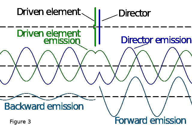 1) Forward Gain is the dB of gain on the Major Lobe. Like all antennas, makers may express this as either gain over an isotropic (dBi) or over a dipole (dBd). Forward gain figures for a Yagi can be huge. As mentioned above, a 5-element Yagi will have (typically) around 9.5 dBd of forward gain. A 10-element Yagi (very easy to do at 70cm) would approach 13 dBd of gain. As a rule, more elements (up to a total of about 15) will give more gain.  2) The 3 dB Beamwidth (often just called the Beamwidth) is the width of the Major Lobe at the points where the forward gain falls by 3 dB and is expressed in degrees. This controls how accurately you must point the Yagi to hear and talk to a desired station. As a rule, more gain leads to a narrower beamwidth. All of these figures interact with each other and sometimes the results of changing, let’s say, the number of elements will have a impact that appears, at first, counter intuitive. It is all of these “fuzzy” values that give Yagis their flexibility. In a physical sense, you can vary many parameters: 1) Length of the DE. This won’t change the performance too much, but it can shift the resonant point of the antenna. Be careful playing with this one because it can easily turn into chasing your tail to get the “perfect” match. There are better ways to do this that we’ll talk about when we get Yagi construction. 2) Lengths of the parasitic elements (REF and DIR). This will vary forward gain, FB ratio, and FS ratio. It will also impact the overall impedance of the array. 3) The number of parasitic elements. The main impact will be on the forward gain and the beamwidth, but it will also affect the impedance of the array. 4) The spacing between the several elements. This impacts the forward gain, beamwidth, FB ratio, and FS ratio. The impact on the impedance is small but not negligible. 5) The diameter of the several elements. This will impact the bandwidth of the array and, to a lesser degree, the impedance. Most Yagis are built from tubing, but you could use wire. Tubing will have a wider bandwidth and simpler mechanical construction than using wire. The above items interact to create the directional pattern of the Yagi array. While I’m not going to delve too deeply into the physics of how this happens, the basics are pretty easy to understand. Please see Figures 3 and 4 which show how the EM field from the DE interacts with the induced EM fields in the REF and DIR elements to create the classic Yagi directional pattern. Essentially, the current in the DE from the transmitter will create an electromagnetic field around the DE. The EM field will induce currents into the several parasitic elements, and currents in the parasitic elements will, in turn, induce currents into the DE and other parasitic elements. Since the parasitic elements are not resonant (remember that the REF is longer and the DIRs are shorter), the phase of the induced currents will be different than the current in the DE. The distance the EM field must travel to/from the parasitic elements also shifts the phase. The end result of adding these out-of-phase fields together is that the shorter DIRs tend to “pull” the EM field toward them while the longer REF “pushes” the EM field away from itself. These multiple EM fields combine to create the pattern for the Yagi. The Simple Dipole Now we’re going to take a look at a few images for the simple dipole. It is important to fully understand the dipole because a Yagi antenna is nothing more than a dipole with some extra elements added to it in order to change its behavior. These images are all taken from EZNEC 5 running on Windows 2000 in a Virtual Box under Linux. All patterns are centered on 146 MHz, and all patterns are based on the antenna being in free space. In all cases, the elements are in the plane of the X axis and the elements are perpendicular to and centered on the Y axis. It is worth noting again that I will be using metric measurements here. Frankly, they make more sense (you can see that the 146 MHz center frequency, in the 2m band, has a wavelength of 2053.37 mm, or just over 2m) and it’s easier to measure 1 mm than 0.04 inches. Yes, I know it’s different than what some of you may be used to, but it ain’t rocket science. Well, rocket scientists do use metric. Except for Lockheed/Martin when building the Mars Climate Orbiter, but I digress... [Click this link to see Figure 5] First, we have Figure 5. This is a screenshot showing the information entered into EZNEC to get the model of the dipole into the system. In the WIRES window, you can see that I have made the element 972 mm long (free space ½ wave for 146 MHz is about 1027 mm but allowing for VF we get 972 mm) and I have centered the element on the X axis, so End 1 is at 486 mm and End 2 is at -486 mm. Also note in the SOURCES box, I have provided 1 source on the DE at the center, that is, 50% from End 1. If you are following along with this article in EZNEC (which I strongly encourage), Figure 5 shows all the things you will need to enter. [Click this link to see Figure 6] Figure 6 is the view of the simple ½ wave dipole. You can see the element has a red circle at its center, and this is the feed point (or source) location. Here you can see the element (Wire 1) lays on the Y axis and its center is at the X axis where the Source is located. You can get to this image in EZNEC by clicking the VIEW ANT button. [Click this link to see Figure 7] Figure 7 shows the classic dipole broadside pattern as discussed in the article about dipoles. Note, however, that the nulls off the ends of the wire are not as deep as many expect, being only about 10 dB down from the main lobes. In the lower left corner of Figure 7, you can see the various gain figures. The dipole, as expected, has a forward gain of 2.13 dBi and the FS ratio of 9.89 dB. This image is at the FF PLOT button. [Click this link to see Figure 8] Next, if you look at Figure 8 you’ll see the SWR plot from 144-148 MHz, the entire 2m band. At the center design frequency (where the green dot is) you will see that the SWR will be 1.53:1 when fed with a 50 ohm feeder (see the upper left corner where you can select between two different feed impedances). In the lower left corner, of particular interest are the two entries shown as Z, or the feed point impedance of the antenna. In this case, the feed point has a complex impedance of 74.43 + j 8.85 Ohms. In other words, the feed point has 74.43 ohms of resistance and 8.85 ohms of inductive reactance. This results in the 1.53:1 SWR when fed with 50 ohm line, but again harking back to the dipole article, we would get a very close match feeding the antenna with 75 ohm coax. Click on SWR in EZNEC to see this. [Click this link to see Figure 9] Lastly, we will look at Figure 9. Figure 9 is very similar to Figure 6, but in Figure 9, the curved purple line above the element is the current distribution through the element. For the dipole, this is a nice, smooth curve starting at zero at one end of the wire, building to a maximum value at the center (where the feed point is) and then falling back to zero at the other end of the element. The importance of this will become obvious as we move forward. This image is also on the VIEW ANT button, but appears only after you have run a FF PLOT. If you have been following along in EZNEC and inputting the several values, congratulations! You have modeled your first antenna with EZNEC!! Building more complex antennas to model is just as easy. In the next part of the Yagi article series, we will get into the modeling much deeper as we explore what happens as we start to add parasitic elements and vary their parameters. Yagi antennas offer many advantages...they can have high forward gain to get you into distant stations with a better signal; A Yagi can have deep nulls to help block interference from sources that might make you unable to communicate; They are easy to build; Smaller Yagi antennas are fairly simple to get in the air; and a Yagi can be made to cover multiple bands in one physical device. The Yagi also improves your reception of distant signals. But no matter if we are talking about receiving a distant station or transmitting to a distant station, remember that a Yagi is NOT omni-directional. You MUST aim the Yagi in the direction you want to work. This implies some kind of system to turn the antenna in the desired direction, and this rotor system can add both complexity and cost to the overall antenna system. Note that there is nothing wrong with having a Yagi pointed in a fixed direction, so long as that’s the only direction you want to work. One example would be linking repeaters via radio...in this case, repeaters A and B will only ever talk to each other, so they might both have Yagi antennas aimed at each other and bolted down. This would give a strong, high reliability link between the two machines. In my opinion, however, the biggest advantage to a Yagi is that the same design—and even the same antenna—can be used for both vertical and horizontal polarization. You simply select if you want vertical polarization (the elements perpendicular to the ground) or horizontal polarization (elements parallel to the ground) when you mount the antenna. You can even put both sets of elements on the same boom so you can switch between horizontal and vertical as desired. And, if you like, you can have a slightly more complicated coax switching system that will give you a choice between horizontal, vertical, and circular polarization (either right or left handed) to fit your needs at the moment...for example, you could select vertical and work the local (or even distant) repeaters, then select horizontal to do a little SSB weak signal work, and then flip over to circular to work a few of the amateur satellites all in a matter of minutes using the same antenna. In our next visit to the Yagi Patch here on the Antenna Farm, we’re going dig deeper into modeling and how parasitic elements impact Yagi performance. Take Care & 73 de KC6UFM Charles AN INTERVIEW WITH JEFF KD2YEI - By Lucca KD2YHZ Here is the interview I did with Bill KD2YEI. Thank you, Bill, for participating. Q: What is your name, Callsign, & Location? A: My name is Bill Critchfield, KD2YEI in Palmyra, New York. Q: How long have your been a ham? A: I have been a ham for 11 months. Got my ticket October 16, 2021 Q: What class license do you hold? A: I hold the Extra Class Q: When did you upgrade your license? A: I upgraded to General November 2021 and Extra March 2022 Q: What got you into Ham Radio? A: I've had radios since I was a kid starting with CB ht's. I worked in the fire service and law enforcement most of life. A few years after I retired I found that I missed the radio part of that. I started in GMRS and wanted to expand. I then started in ham radio. Q: What do you enjoy most about amateur radio? A: I enjoy the people, their willingness to help others, the variety of the type of communications you can get into and making those distant contacts Q: What radio equipment do you currently have? A: I have a Icom 7300, Diamond HFV-5H antenna for HF, a Icom 5100A with a j-pole, a Icom 5100A in my truck, Anytone AT-D878UV II Plus, Wouxun KG-UV9D ht's for 2m/70cm and a RFinder B1+ Q: What got you into the hobby? A: I missed being around radios, being retired I wanted to get into a hobby and wanted other means of communication. Q: What hobbies do you have outside of Ham Radio? A: Outside of radio, I love to ride motorcycles, take trips and do most anything outdoors. Q: What keeps you coming back for the ECR Morning Brew? A: I keep coming back to the Morning Brew because of the hosts, the people and the questions. Thanks again, Bill. More interviews coming soon! FREE GENERAL EXAM, ONLINE CLASS! - Submitted by Steve K2EJ Isn’t it time to upgrade your license from Technician to General? A free, weekly, live, Amateur Radio General Class Licensing course on Zoom will begin on Thursday, Oct 27 and will run through Thursday, January 5. There will be 9 sessions, with two breaks for holidays. The three-hour sessions will start at 6:30 PM Eastern Time. Sessions will be recorded. These are the classes that we have been holding for years sponsored by the National Electronics Museum. Those wishing to sign up should email roland.anders@comcast.net. Thanks. 73, Rol Anders, K3RA HAM RADIO OPERATOR HELPS WOMAN IN FLORIDA STRANDED DURING HURRICANE IAN Submitted by Kevin KE7K https://www.wgal.com/article/ham-radio-operator-helps-woman-in-florida-stranded-during-hurricane-ian/41616071# AMATEUR RADIO OPERATORS INVITED TO PARTICIPATE IN SCIENTIFIC EXPERIMENTS Taken from The ARRL Letter dated October 20, 2022 The High-frequency Active Auroral Research Program (HAARP) will be conducting their largest experiment and research campaign from October 19 - 28, 2022. Amateur radio operators are invited to listen and participate. The research will last for 10 days and include 13 experiments, with transmissions taking place between 1400 - 0600 UTC daily. The transmission experiments include moon bounce, Jupiter bounce, HF ocean scatter, and ionosphere satellite interactions. Amateur radio operators are being asked to monitor the times of the transmissions and signal quality. Reports can be filed electronically, and a special QSL card will be sent for participation. 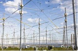 This
will be the most scientifically diverse campaign ever conducted at
HAARP. Particularly notable experiments include a first-of-its-kind
attempt to bounce a signal off of Jupiter, investigation into possible
causes of the airglow phenomenon known as STEVE (Strong Thermal
Emission Velocity Enhancement), and testing the feasibility of using
radio transmissions to measure the interiors of near-Earth asteroids. This
will be the most scientifically diverse campaign ever conducted at
HAARP. Particularly notable experiments include a first-of-its-kind
attempt to bounce a signal off of Jupiter, investigation into possible
causes of the airglow phenomenon known as STEVE (Strong Thermal
Emission Velocity Enhancement), and testing the feasibility of using
radio transmissions to measure the interiors of near-Earth asteroids."The October research campaign is our largest and most diverse to date, with researchers and citizen scientists collaborating from across the globe," said HAARP Program Manager Jessica Matthews. The number of experiments is the highest so far under the 5-year, $9.3 million grant awarded last year by the National Science Foundation to establish the Subauroral Geophysical Observatory at HAARP. The observatory's purpose is to explore of Earth's upper atmosphere and geospace environment. An overview of all of the experiments can be found at the HAARP website. See the following document (PDF) for a more detailed listing of the experiments and technical data. Participating amateur radio operators can request a QSL card and send reception reports to HAARP, P.O. Box 271, Gakona, AK 99586. HAARP is a scientific endeavor aimed at studying the properties and behavior of the ionosphere. Operation of the research facility was transferred from the US Air Force to the University of Alaska Fairbanks on August 11, 2015, allowing HAARP to continue with exploration of ionospheric phenomenology via a land-use cooperative research and development agreement.  YACHT NEWS for October 22, 2022 Young Amateurs Communications Ham Team, K8KDZ, Sailing Through Radio Waves Connecting Young Hams, Creating Friendships, Expanding the Voice of Youth in Ham Radio Inspiring Youth with Enjoyment & Technology of Ham Radio -------------------- We can be found on Facebook, evening chat sessions & Saturday youth net, YACHT News -------------------- NET REVIEW... Good session with 24 stations logged, 20 with audio. Youth checking in: 2W0KYH, KE8RJU, K9ZN, KC3RAP, KE0ZNV, KJ7MPQ, KJ7MFU, VA3BHT, NC8R, KN4VKW, KN5VKY, KF0JFQ VU3EWS and others. CHAT SESSIONS... Monday: Youth ops, NC8R, KC3RAP, KF0JYQ, KD2YHZ, KE8LQR and 5 other. Tuesday: Only 6 stations connected: KC3RAP, KF0JFQ, KE0ZNV, K3TEL, KC3CDU, K5NO. Hope we can increase that a bit for Wednesday. Bradley KC1PEH will run the session tonight, give him a call. YACHT MEMBER UPGRADE... congratulations to Dylan KF0JFQ on his General class upgrade. Here is a photo of him and his Mom who encouraged him along the path. Check out his updated QRZ page http://www.qrz.com/db/kf0jfq 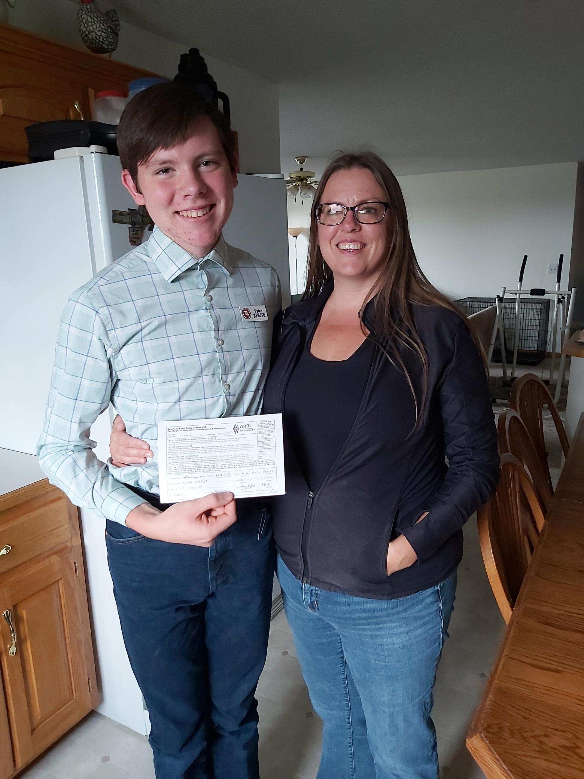 Dylan & Mom N6RWC... Ryan achieved this major Scout award this weekend. Order of the Arrow. Excellent achievement.  LYLE ON SCR... 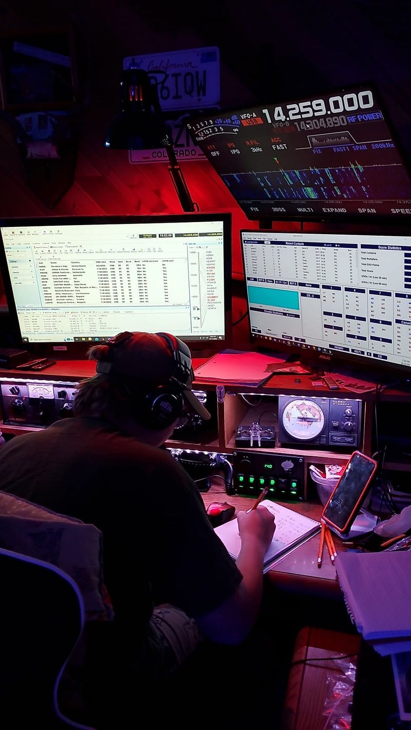 Photo of KE0ZNV working a pileup in the School Club Roundup on Monday. His score at the end of Monday [link] And here is a recording of Lyle working SCR. Thanks to Randy K0RWB for this https://youtu.be/fSJ34zCI978 JASON COLEMAN PLAYS FLOYD CRAMER... the grandson of the famous country artist plays songs he made popular in the 70's. Don't miss Jason's young son Avery at the beginning and playing "Last Date" at the end. [link] MILITARY DAD SHOWS UP UNEXPECTEDLY... A wonderful reaction to seeing her Dad https://www.facebook.com/watch/?v=12421903696876 MANIANA OF THE FRENCH FAMILY... This 12 yr old sings a beautiful "Smile" https://www.facebook.com/watch/?v=1297414897755530 A JOTA STORY FROM ENGLAND... You can read or listen to this one [link] BACK PORCH PICKINGS... this musical link showcases Meagan Taylor (Chet Atkin's niece) and her 3 kids. Great music from a relative of a Nashville legend, one of my favorites. https://www.facebook.com/MeaganTaylorMusic/videos/313649319699941/ -- 73, Ed Engleman KG8CX http://yachthams.webstarts.com/index.html http://w8pif.webstarts.com/index.html http://www.qrz.com/db/k8kdz HOW CAN YOU HELP OUT WITH THE NEWSLETTER? If you have any interest in giving us a hand, please send an email to K2SHF. Send us links, articles, pictures, anything really. And if you have knowledge in a subject that you think our readers would find interesting, perhaps you could write some articles. "This is a team effort". |
| FACILITATORS Dick WB2JPQ Henry WB4IVB Emil WA2UPK Bob KB3SNM Tony W2KJV Kevin VE3BZ Paul W4END David KB4FXC Kevin KE7K Joe KO4FRR Mike K2CMT Michael K2SHF Keynon KB5GLC Dan KD2VNU Caleb KO4UYJ Scott W2BLT |
ECR ACCESS IRLP 9050 AllStar 27339, 45192, 45225 Echolink WB2JPQ-R(57780), WB2JPQ-L(375103) DMR Brandmeister 3129973 DMR TGIF 9050 System Fusion 44444, 92805 DStar XRF(XLX)256E HamShack Hotline 94049 P25 31582, 9050 M17 M17-ECR Module A Hams Over IP 15001 NETS ECR Tech Net Tuesdays 8PM ET Morning Brew Mon-Fri 7AM ET ECR Pop-Up Net Happens at random times on random days 40m ECR Net Mondays at 8PM ET on 7245 KHz +- LSB |
WEBPAGE http://eastcoastreflector.com ZOOM ROOM Open 24/7. All are welcome! ID: 83929643320 Password: 193414 http://bit.ly/ecrdaily MERCH SHOP http://bit.ly/ecrshop TECH NET LOG http://bit.ly/ecrtechnet YOUTUBE CHANNEL http://bit.ly/ecrYouTube |
